Table of Contents
Advertisement
Quick Links
Advertisement
Table of Contents

Related Manuals for RECO SensorLine RM-DPC Micro FP

Summary of Contents for RECO SensorLine RM-DPC Micro FP
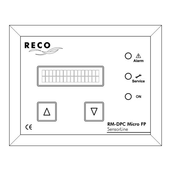
- Page 2 Operating and installation instructions Differential pressure monitor RM-DPC Micro FP SensorLine...
-
Page 3: Table Of Contents
RM-DPC Micro FP Documentation Table of contents 1 Safety instructions ........................... 3 2 Equipment specification .......................... 3 3 Assembly ..............................4 4 Step-by-step installation .......................... 4 5 Step-by-step settings ..........................6 5.1 Function in delivery status ......................6 5.2 Display and setting elements ......................6 5.3 Setting parameters ........................ -
Page 4: Safety Instructions
Otherwise the equipment may be damaged. 2 Equipment specification The devices in the SensorLine RM-DPC Micro FP series are differential pressure controllers designed for use in robust, industrial environments. They are used for measuring, visualising and controlling non- aggressive, gaseous media in the excess pressure and insufficient pressure ranges. -
Page 5: Assembly
RM-DPC Micro FP Documentation 3 Assembly 4 Step-by-step installation Connecting the supply voltage RDN 10000531 13.05.2013... - Page 6 RM-DPC Micro FP Documentation More connections Signal cables may not be run parallel to power cables. Tighten all cable glands in use to ensure that the cables are properly enclosed and that protec- tion rating IP-66 is guaranteed. Cable glands that are not in use must be closed or replaced with blank plugs. ...
-
Page 7: Step-By-Step Settings
RM-DPC Micro FP Documentation 5 Step-by-step settings 5.1 Function in delivery status The functions of a differential pressure dependent two-position controller and a differential pressure mon- itor are active on delivery. Two-position controller: If the increasing differential pressure exceeds the ∆p max switch point (factory ... - Page 8 RM-DPC Micro FP Documentation "Service" LED This LED flashes if the set number of service hours has elapsed. This LED goes out when the service hours counter is reset to 0 hrs. In order to do this, Parameter 10 "Maintenance acknowledge ?"...
-
Page 9: Setting Parameters
RM-DPC Micro FP Documentation 5.3 Setting parameters For more on this refer to points "Configuration keys" on page 7 RDN 10000531 13.05.2013... -
Page 10: Parameter List
RM-DPC Micro FP Documentation 5.4 Parameter list Text on the display Explanation Factory setting Setting range dP-control, 01 01 Contr. type Device function dP-control. dP-monitor 150 Pa ... ∆p min switch point 02 02 dP min 700 Pa (dP max - 50 Pa) 200 Pa ... -
Page 11: Details On Device Function
RM-DPC Micro FP Documentation 6 Details on device function 6.1 Two-position controller (Parameters 01, 02, 03, 04, 05) In order to implement a differential pressure dependent two-point controller with the switch points ∆p min and ∆p max, Parameter 01 "Contr. type" must be configured to "dP control.". (For more on this refer to ... -
Page 12: Differential Pressure Monitor (Parameters 01, 04, 05)
RM-DPC Micro FP Documentation 6.2 Differential pressure monitor (Parameters 01, 04, 05) In order to implement a differential pressure monitor with the switch points ∆p min alarm (for a ∆p pre- alarm) and ∆p max alarm, Parameter 01 "Contr. type" must be configured to "dP monitor". (For more on ... -
Page 13: Timer Function (Parameters 06, 07, 08)
RM-DPC Micro FP Documentation 6.3 Timer function (Parameters 06, 07, 08) In addition to the differential pressure dependent two-position control, the timer function also makes it possible to carry out time-controlled forced cleaning. The timer works independently of other device func- tions. -
Page 14: Text Messages On The Display
RM-DPC Micro FP Documentation 8 Text messages on the display 8.1 Operating messages Display Explanation Appears after the power is switched on and remains for approx. 1 se- RM-DPC Micro cond. The RM-DPC Micro FP can start up and perform a self-test during Software #.## this time. -
Page 15: Glossary
RM-DPC Micro FP Documentation 9 Glossary Term Explanation Bulkhead connectors Connections for attaching the differential pressure measurement hoses. Configuration Parameter settings Differential pressure monitor Device function that monitors two configurable ∆p switch points. Differential pressure ∆p Difference between the pressure on the clean gas side and the pressure on the crude gas side of the filter. -
Page 16: Technical Specifications
RM-DPC Micro FP Documentation 10 Technical specifications RM-DPC 5000 Micro FP RM-DPC 10000 Micro FP ∆P measuring range Full scale output configurable from For the range 1000 Pa ... 5000 Pa 1000 Pa ... 5000 Pa the full scale output is configurable in 500 Pa increments in 500 Pa increments For the range 5000 Pa ... - Page 17 RM-DPC Micro FP Documentation Disclaimer The contents of this documentation has been verified for correctness and completeness. Nevertheless, errors can not be excluded so that we cannot guarantee the correctness of this information. Subject to alterations at any time. RDN 10000531 13.05.2013...
Need help?
Do you have a question about the SensorLine RM-DPC Micro FP and is the answer not in the manual?
Questions and answers