Table of Contents
Advertisement
Quick Links
Advertisement
Table of Contents

Related Manuals for Gewiss Chorus GW 90797A


Summary of Contents for Gewiss Chorus GW 90797A
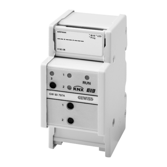
- Page 1 KNX logic module - DIN rail mounting GW 90797A Technical Manual...
-
Page 2: General Parameters
General The setting examples shown in this application de- The KNX logic module can be programmed with this scription serve merely as guidance and may devi- application. ate from the settings actually required. In complex KNX installations, the logic module serves The bold values are the values set during factory to establish special logic operations between sensors configuration. -
Page 3: Gate Function
Input behaviour Output behaviour The behaviour of the input after re-establishment of the The user can select whether the gate sends a telegram bus voltage can be determined here. upon opening or not and whether the value of the output is inverted. -
Page 4: Internal Connection
Example 1: Block 1 and block 2 invert the input values Internal connection in each case. The output from block 1 is internally con- The internal connection function serves to reduce the nected to the input from block 2. number of group addresses and telegrams, thereby Block 1 and 2 are updated simultaneously. -
Page 5: Logic Function
Receipt of an input telegram: An output telegram will be Logic function sent after receipt of an input telegram, regardless of the logic result. This means that cyclical input telegrams Object name Size Flag Direction also trigger cyclical output telegrams (same cyclic inter- Logic object 1...8 1 bit Input... -
Page 6: Basic Applications
Basic applications Parameter Setting The logic function is particularly suitable for summaris- Gate function 1= closed, 0= opened 0 = closed, 1 = opened (inverted) ing messages (e.g. the lighting status in rooms), linking Send output telegram if conditions (e.g. rain or wind sensor activates a safety gate opens function) or programming an additional toggle between manual and automatic (e.g. - Page 7 Application example Example: Time delay if 0 and 1. Both telegrams are for- warded with a time delay. • A light-sensitive switch switches the lighting on auto- matically. Time delay • The light is switched off between 23:00 and 06:00. if 0 and 1 •...
- Page 8 Parameter Example 3: 1 -> toggle / 0 -> -. 0telegrams are filtered out. The 1telegrams toggle between 0 and 1. Time delay and filter func- tion Filter Parameter Setting 1 -> toggle / 0 -> 1 Time delay if 1 if 0 if 0 and 1 Filter...
-
Page 9: Converter Function
Converter function Internal connection Parameter Setting Object name Size Flag Direction Output converter function block Nothing 1 is connected to Logic block 1 logic object 1 ... Converter input/ 1 bit Input Logic block 10 logic object 1 output object 2 bit Output 1 byte... -
Page 10: Multiplexer Function
Example 1: The gate is closed and the delay time is ac- Multiplexer function tive. The gate is open and the time has not yet elapsed. An output telegram will be sent when the delay time has Object name Size Flag Direction elapsed. - Page 11 Parameter B is the input object this time. A -> B B -> A Multiplexer block 1 Parameter Setting Type of multiplexer object 1 bit Object A 2 bit Objekt A 4 bit 1 byte 2 byte 4 byte Control object = "0" A / B Object B A ->...
- Page 12 As standards, specifications and designs develop from time to time, always ask for confirmation of the information given in this publication. GEWISS - MATERIALE ELETTRICO +39 035 946 111 sat@gewiss.com +39 035 946 260 8.30 - 12.30 / 14.00 - 18.00...
Need help?
Do you have a question about the Chorus GW 90797A and is the answer not in the manual?
Questions and answers