
Related Manuals for Paragon G Series

Summary of Contents for Paragon G Series
- Page 1 Installation Operation Manual G-Series Gear Pump Models: G125 G125 Series Operation Manual August 07, 2019...
-
Page 2: Introduction
Congratulations on your new Paragon purchase... -
Page 3: Table Of Contents
Table of Contents Section Page Introduction..............Safety Notice..............Warning Labels............. Initial Installation Considerations........Maximum Capabilities..........Pre-Operation Checks..........Relief Valve Adjustment..........Model Number Construction…………………………….. Dimensions..............Component Breakdown……………..…………………… 11-12 Replacement Parts............Warranty................ -
Page 4: Safety Notice
Safety Notice This manual is designed to be read to its entirety prior to installation or operation of this product. Do NOT install or operate prior to reading this manual completely - injury or property damage can occur. Use adequate protection and safety equipment while performing the steps indicated in this manual. - Page 5 Warnings NOTICE WARNING: Warning Instructions listed on this page must be reviewed by ALL operators. Safety instruction tags were attached to your unit prior to shipment. DO NOT remove, paint over or obscure in any manner. Failure to heed these warnings could result in serious bodily injury to the personnel operating and maintaining this equipment.
-
Page 6: Initial Installation Considerations
Fig. 1 Hydraulic Motor Orientation Considerations Paragon • The G125 is a hydraulic driven gear pump and is not 302-009 & 302-010 intended for use with a driveline. (See pg 11 for hydraulic... -
Page 7: Maximum Capabilities
Initial Installation Considerations / Continued Mounting Considerations • Mount the unit on a rigid, heavy base to provide support and absorb shock. The base should be designed for rigidity across a flat even surface. • Mounting kits are available with directional control valve mounting and ball valve mounting. -
Page 8: Pre-Operation Checks
Pre-Operation Checks • Ensure hydraulic motor mating surfaces are clean and free from debris • Check hydraulic motor rotation.(Fig. 1) • All hydraulic hoses are installed according to manufacturer specifications and supported properly. • G125 Pump mounting feet are flat against the mounting surface. •... -
Page 9: Relief Valve Adjustment
Relief Valve Adjustment Factory Relief Valve Settings for the G125 The Factory Setting for the Chemical Pump Relief valve is as follows Factory Relief Valve Product Pump Setting G125-1A 80 PSI G125-1B 100 PSI Determine Pressure limits for G125 Identify Spec # located on the ID Plate of G125 at the bottom left corner, the last 2 digits identify the pressure limits of the Relief Valve Spring 1A or 1B as shown in picture below. -
Page 10: Model Number Construction
Model Number Construction G125 Product Pump Type Hydraulic Motor G125 Gear, 125 PSI & Trunk -X - No Hydraulic Motor -01 - 4.9 cu” Inlet -02 - 6.2 cu” X - None B - Elbow 2” NPT Mounting Bracket F - Elbow 3” Port CI X - None G - 2”... -
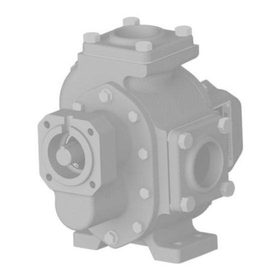
Page 11: Dimensions
Dimensions Approx. Weight Model Port Size (No Flanges, Steel Shaft) ” ” ” 1” ” ” 7 ” 3” 90 lbs 2 ” w/o Flange ” w/ Trunk) G 125 76.2 38.1 163.58 25.4 6.35 139.7 269.75 194.82 40.82 Kg (447.30 w/ Trunk) Flange Hydraulic Trunk is SAE “A”... -
Page 12: Component Breakdown
Component Breakdown... - Page 13 Component Breakdown/Continued Item Part # Description 297-001 Outer Bearing Retainer 510-005 Ball Bearing 297-000 Inner Bearing Retainer 555-005 Triple Lip Shaft Seal 192-003 Hex Head Cap Screw 228-031 Washer Head Cap Screw 274-001 Hollow Dowel Pin 501-008 Back Plate 298-003 Outer Shaft Key 503-002 Drive Shaft (Steel)
-
Page 14: Replacement Parts
Replacement Parts Back Plate Assemblies Includes: (1) Back Plate, (1) Short Bushing, (1) Long Bushing Part# Description 501-006 Back Plate Assembly w/ Bronze Bushings 501-007 Back Plate Assembly w/ Carbon Bushings Face Plate Assemblies w/ Relief Valve Includes the following: (1) Face Plate, (2) Long Bushings, complete relief valve assembly Part# Description 581-014... -
Page 15: Warranty
Warranty Subject to the terms and conditions hereinafter set forth in General Terms of Sale, Paragon Tank Truck Equipment LLC (the Seller) warrants products and parts of its manufacture, when shipped and its work (including installation and start-up) when performed, will be of good quality and will be free from defects in material and workmanship. This warranty applies only to Seller’s equipment, under use and service of products, for a period as stated in the table below.
Need help?
Do you have a question about the G Series and is the answer not in the manual?
Questions and answers