
Related Manuals for LAZY MAISONS LM-BZS3


Summary of Contents for LAZY MAISONS LM-BZS3
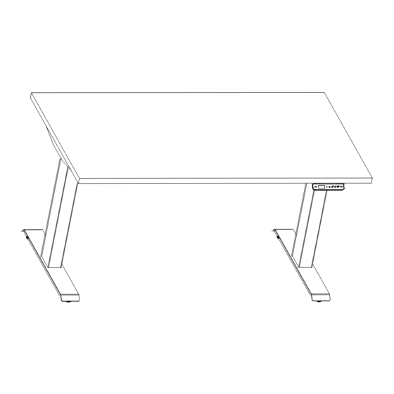
- Page 1 LAZY MAISONS HEIGHT ADJUSTABLE TABLE STRAIGHT STAGE T LEG BASE LM-BZS3 Model Number : Please Read Instructions Before Use ASSEMBLY INSTRUCTIONS...
-
Page 2: Tools Needed
Tools Needed possible product. Introduction including My-Hite, a height adjustable table that allows for standing or sitting while working. User Notes 1. As with all power-operated products, please follow instructions closely and handle with care. 2. When moving tables, please lift the tables, do not drag or tilt the table on one leg as Socket Head misalignment may occur. -
Page 3: Parts List
Parts List Socket button head bolt Connecting Beam Column Leg Feet Crossbeam M6×35 E (2 pcs) A (2 pcs) B (2 pcs) D (2 pcs) C (8 pcs) Rubber Wood Screw Metal Screw Longitudinal Beam Control Box Display Washer M4.8×19 M10×16 (2 pcs) (1 pc) -
Page 4: Installation Steps
Installation Steps Step 1 Step 3 Stretch D crossbeams to where you think it is ,then use (12) wood screws,4.8 mm through H Rubber W saher to secure Longitudinal Beams and D crossbeams to Step 2 worksurface as shown.Repeat on other side. longitudinal beams into crossbeams assembly and slide to lock into place. - Page 5 Step Step Pressure Retainer Lever Column Leg Crossbeam...
- Page 6 Step7 Step10 Attach B feet to A column leg with C (8) socket button head bolts, M65. Tighten bolts securely.Repeat Secure J Control Box in the desired location with I (2) Wood Screw,M4.8×19. on other side. Step8 Secure K Display in the desired location with L (2) Wood Screw,M3.5×15 with washers. Step9 Use Q Wood Screw,M3.5×16 and O Sticky Card,or Q(4)Wire Clips to secure wires below the worksurface as shown.
- Page 7 Step 1 Turn table right side up, adjust the glides as necessary, and plug the power cord into a 100-240v outlet.Make sure the length of the plug-in cord is appropriate to both reach the outlet, AND for Power Control Wires the distance the table will travel up and down.
- Page 8 2) Set Memory Position 5) Set Minimum Height 1. Use & buttons to adjust the table. 1. Use & buttons to adjust table to desired minimum height. 2. Press S, then press button 1 or 2 or 3 or 4 within next 3 seconds to set height for that #. 2.
-
Page 9: General Tips
roubleshooting stage Error Code Cause Solution Explanation Check the cable connections between leg and computer. Reset Connection ssue he leg is disconnected rom the control box. display. If problem persists contact ustomer ervice. Let motor rest or 10 min. hen try again. Continous peration Continous operation or 5 min.
Need help?
Do you have a question about the LM-BZS3 and is the answer not in the manual?
Questions and answers