Advertisement
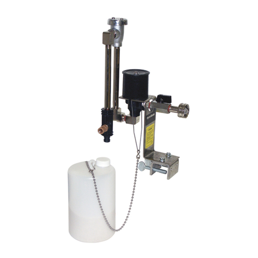
Package Contains
- Proportioner with U-clamp for mounting
- Float with chain
- Suction tube with foot valve -- 9 ft.
- Discharge tube -- 2 ft.
- Metering tip kit (14 tips)
- Production information sheet
Installation
- Mount the unit in a level position on the side of a reservoir. The U-clamp may be repositioned or removed as necessary.
- Install a minimum ½" ID water hose between the inlet threads and the water spigot. Minimum water pressure required to properly operate the proportioner is 25 PSI (flowing).
- Attach the end of the discharge tube with the clamp and flooding ring to the discharge barb on the eductor.
- Insert the foot valve end of the suction tube into the concentrate container. (The level of the concentrate must be below the level of the eductor, or the proportioner will continue to siphon concentrate after it is turned "off".)
- Select a metering tip (see next two sections) and screw it into the suction stub on the eductor body.
- Slide the open end of the suction tube over the suction stub.
- Adjust the bead chain length to position the float at the desired level of solution. To prevent foaming, be certain that the solution level will always be above the point of discharge. Be sure float mechanism is not hampered by water turbulence caused by discharging solution. It may be necessary to baffle the float from the discharge in order for the unit to work properly.
Metering Tip Selection
The final concentration of the dispensed liquid is related to both the size of the metering tip opening (orifice) and the viscosity of the liquid being siphoned. If product viscosity is noticeably greater than that of water, consult the procedure for Measurement of Concentration on the next page to achieve your desired water-to-product ratio. For water-thin products, use the chart below as a guideline. Because such factors as inlet water pressure and temperature can affect dilution ratios, the figures listed below are only approximate. Test the actual dilution you are achieving using the Measurement of Concentration procedure for best results. Two undrilled, clear tips are supplied for drilling sizes not listed.
| Tip Color | Drill Size | Approx. Ratio @ 40 PSI, water-thin viscosity |
| No tip | 4:1 | |
| Gray | 30 | 5:1 |
| Black | 40 | 6:1 |
| Beige | 50 | 8:1 |
| Red | 55 | 17:1 |
| White | 57 | 23:1 |
| Blue | 60 | 25:1 |
| Tan | 65 | 36:1 |
| Green | 70 | 48:1 |
| Orange | 72 | 64:1 |
| Brown | 74 | 75:1 |
| Yellow | 76 | 90:1 |
| Purple | 80 | 120:1 |
| Pink | 87 | 240:1 |
Measurement of Concentration
You can determine the dispensed water-to-product ratio for any metering tip size and product viscosity. All that is required is to operate the primed dispenser for a minute or so and note two things: the amount of dispensed water/product mixture, and the amount of concentrate used in preparation of the solution dispensed. The water-to-product ratio is then calculated as follows:

Dilution ratio, then, equals X parts water to one part concentrate (X:1). If the test does not yield the desired ratio, choose a different tip and repeat the test.
Alternative methods to this test are
- pH (using litmus paper), and
- titration.
Contact your concentrate supplier for further information on these alternative methods and the materials required to perform them.
Operation
Open the water supply ball valve. When the solution in the reservoir reaches the level set by the float, the valve will close. This will stop the water flow and siphoning of concentrate. When withdrawal of solution from the reservoir causes the level to drop more than 1-1/2 inches, the valve will open, and the reservoir will be refilled to the previous, pre-set level. This cycle will be repeated automatically until the supply of concentrate is depleted. The ball valve should be fully closed when changing metering tips or concentrate container, when reservoir is drained, or when the unit is not in use.
Troubleshooting
| Problem | Probable Cause | Remedy |
|
|
|
|
|
|
|
|
|
|
|
|
| * In hard water areas, scale may form at the discharge of the eductor. This scale may be removed by soaking the eductor in a descaling solution or by running the descaling solution through the system. If descaling solution is educted through the system, flush the unit by educting water only before returning the system to regular use. | ||
Parts Diagram/List

| KEY | PART NO. | DESCRIPTION |
| 1 | 238100 | strainer washer |
| 2 | 506500 | hose swivel |
| 3 | 502000 | ball valve |
| 4 | 360900 | nipple |
| 5 | 10080500 | magnet parts kit
|
| 6 | 5030-K | mounting bracket kit (specify model 511) h. Z bracket i. U clamp j. lockwasher (not shown) k. screw m. thumbscrew |
| 7 | 665520 | valve parts kit n. valve guide ("bonnet") p. armature spring q. armature r. diaphram |
| 8 | 520000 | water valve body |
| 9 | 505600 | street elbow |
| 10 | 519000 | close nipple, 1/4" |
| 11 | 506000 | elbow |
| 12 | 505900 | nipple, 6" |
| 13 | 506300 | vacuum breaker |
| 14 | 440121 440100 440101 | eductor assembly
|
| 15 | 690015 | metering tip (kit) |
| 16 | 5057-A | discharge tube assembly |
| 17 | 5058-9A 505809 250006 10076301 250700 | suction tube assembly
|
| 18 | 5043-A 507200 | float & chain assembly
|
Documents / ResourcesDownload manual
Here you can download full pdf version of manual, it may contain additional safety instructions, warranty information, FCC rules, etc.
Advertisement

Need help?
Do you have a question about the 511 and is the answer not in the manual?
Questions and answers