
Subscribe to Our Youtube Channel
Related Manuals for Georg Fischer Piping Systems CONTAIN-IT Plus


Summary of Contents for Georg Fischer Piping Systems CONTAIN-IT Plus
- Page 1 CONTAIN-IT Plus Kugelhahn Typ 546 CONTAIN-IT Plus Bedienungsanleitung Ball Valve Type 546 Instruction Manual...
-
Page 3: Table Of Contents
Instruction Manual Einleitung ..........................2 Aufbau CONTAIN-IT Plus Kugelhahn 546 ................3 Installation .........................4 Schritt 1: Einbau des CONTAIN-IT Plus Kugelhahns 546 ..........4 Schritt 2: Vorbereitung der Druckprüfung................5 Schritt 3: Druckprüfung der Innenleitung................7 Schritt 4: Zusammenbau des CONTAIN-IT Plus Kugelhahns 546........7 Aus- und Einbau des Kugelhahns..................9 4.1. -
Page 4: Einleitung
Muffenschweissen PE80, PP-H, PVDF Muffenkleben PVC-C, PVC-U Nachfolgend ist die: • Installation und Druckprüfung des CONTAIN-IT Plus Kugelhahn 546 • Ausbau und Wiedereinbau im Falle einer Leckage • Nachrüstung der Armatur auf automatische Antriebe beschrieben. Wir weisen Sie darauf hin, dass Sie bei jedem Ein- bzw. Ausbau der Doppelrohr-Armatur die Einbaubedingungen sowie die Sicherheits- und Warnbedingungen in der beigelegten Montage- und Betriebsanleitung für den... -
Page 5: Aufbau Contain-It Plus Kugelhahn 546
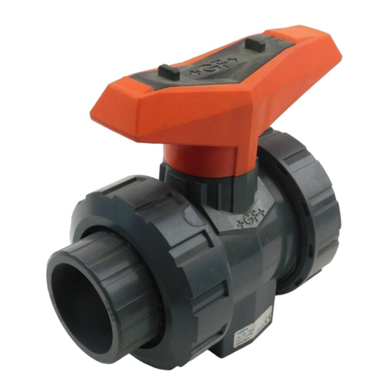
2. Aufbau CONTAIN-IT Plus Kugelhahn 546 1. Schutzgehäuse 2. Zapfen 3. Einlegteil 4. Einschraubteil 5. Überwurfmutter Schutzgehäuse 6. Handhebel 7. Muttern und Schrauben (zur Befestigung des Hebels) 8. Abstützungen PE 9. Kugelhahn Typ 546 (Zentralteil) 10. Überwurfmutter Kugelhahn Typ 546 11. -
Page 6: Installation
Bevor der Doppelrohr Kugelhahn 546 in Betrieb genommen werden kann, sind die folgenden 4 Schritte zum Einbau notwendig: Schritt 1: Einbau des CONTAIN-IT Plus Kugelhahns 546 Beachten Sie, dass die Kugelhahnstellung auf „AUF“ sein muss (Abbildung 1)! Zuerst wird das Innenrohr des Kugelhahns mit dem Innenrohr der Doppelrohrleitung verbunden. -
Page 7: Schritt 2: Vorbereitung Der Druckprüfung
Schritt 2: Vorbereitung der Druckprüfung Vorgehensweise: 1. Achten Sie darauf, dass der rote Handhebel parallel zur Hauptleitung steht. (Abbildung 1). Abbildung 1 2. Lösen Sie die Muttern am Handhebel und entfernen Sie diesen. (Abbildung 2). Abbildung 2 3. Lösen Sie die Überwurfmuttern des Schutzgehäuses beidseitig und schieben Sie diese und das Einlegteil zur Seite. - Page 8 5. Ziehen Sie den Zapfen aus dem Gehäuse. Eine Einkerbung am Zapfen ermöglicht die Verwendung eines Schrauben- drehers. (Abbildung 5). Abbildung 5 6. Schieben Sie das Gehäuse zur Seite des Einlegteils. Der Kugelhahn ist nun zugänglich (Abbildung 6). Abbildung 6 6/27...
-
Page 9: Schritt 3: Druckprüfung Der Innenleitung
DVS 2210-2 mit Hinweis auf DVS 2210-1, Beiblatt 2, sowie die Anweisungen in der oben erwähnten Montage- und Betriebsanleitung für den Kugelhahn Typ 546. Nach erfolgreicher Druckprüfung folgt nun Schritt 4: Schritt 4: Zusammenbau des CONTAIN-IT Plus Kugelhahns 546 1. Schieben Sie das Gehäuse über den Kugelhahn. (Abbildung 7). Abbildung 7 2. - Page 10 Abbildung 9 3. Kontrollieren Sie, ob der Zapfen mit den seitlichen Führungen des Aufsatzes bündig ist. (Abbildung 10). Abbildung 10 4. Schrauben Sie das Einschraubteil in das Schutzgehäuse (Linksgewinde!) und ziehen es mit dem Zapfenschlüssel an. (Abbildung 11). Abbildung 11 5.
-
Page 11: Aus- Und Einbau Des Kugelhahns
4. Aus- und Einbau des Kugelhahns 4.1. Öffnen des Schutzgehäuses Vorgehensweise: siehe Kapitel 3 - Schritt 2 4.2. Ausbau des Kugelhahns Vorgehensweise: 1. Überwurfmuttern des Kugelhahns lösen. 2. Kugelhahn aus der Innenleitung nehmen 3. Revisionsarbeiten entsprechend der Bedienungsanleitung des Kugelhahns Typ 546 durchführen 4.3. -
Page 12: Nachrüstung Von Antrieben Auf Den Contain-It Plus Kugelhahn 546
5. Nachrüstung von Antrieben auf den CONTAIN-IT Plus Kugelhahn 546 Der CONTAIN-IT Plus Kugelhahn 546 kann mit den Antrieben EA11, EA21 und PA21 gemäss nachfolgender Beschreibung aufgerüstet werden. Bitte beachten Sie jeweils auch die Anleitungen der jeweiligen Antriebe. Zur Aufrüstung eines Antriebes benötigen Sie das Adapter Set 700 238 796. Dieses Adapter Set beinhaltet folgende Teile: •... - Page 13 3. Stecken Sie die Kupplung in den Anschluss des Antriebs. (Abbildung 16). Abbildung 16 4. Montieren Sie die Adapterplatte mit vier Senkschrauben an den Antrieb. (Abbildung 17). Abbildung 17 5. Setzen Sie die Reduzierhülse auf den Zapfen des Kugelhahns. (Abbildung 18). Abbildung 18 6.
- Page 14 7. Der Doppelrohr Kugelhahns 546 und der Antrieb sind nun betriebsbereit. (Abbildung 20). Abbildung 20 12/27...
-
Page 15: Ersatzdichtungen Für Den Contain-It Plus Kugelhahn 546
6. Ersatzdichtungen für den CONTAIN-IT Plus Kugelhahn 546 6.1. Zapfen (siehe S.3 Nr. 15) Dimension Kugelhahn Artikelnummer Menge Dimension Beschreibung d20/50 – d32/50 748 410 103 3.54mm x 29.75mm O-Ring EPDM 749 410 103 3.54mm x 29.75mm O-Ring FPM d40/75 – d63/110 748 410 027 3.54mm x 37.69mm... -
Page 17: English Version: Please Go To
Removing the Ball Valve Type 546.................23 4.3. Re-installing the Ball Valve Type 546 ..............23 Upgrade the CONTAIN-IT Plus Ball Valve Type 546 with an actuator ......24 5.1. Procedure .......................24 Spare part seals for the CONTAIN-IT Plus Ball Valve Type 546 ........27 6.1. -
Page 18: Introduction
PE80, PP-H, PVDF Solvent cementing PVC-C, PVC-U The following points are described in this manual: • installation and pressure testing of the CONTAIN-IT Plus ball valve • removing and reinstalling, e.g. in case of a leak • upgrade the valve with actuators. -
Page 19: Design Of The Contain-It Plus Ball Valve 546
2. Design of the CONTAIN-IT Plus Ball Valve 546 1. protective housing 2. stem 3. union end 4. union bush 5. union nut of protective housing 6. hand lever 7. nuts and screws (to fix the hand lever) 8. support pieces PE 9. -
Page 20: Installation
3. Installation Before putting the double containment valve into operation, the following 4 steps are required to install the CONTAIN-IT Plus ball valve: Step 1: Valve mounting Make sure the ball valve is in the “OPEN“ position (Fig. 1)! First the inner pipe of the ball valve is joined with the inner pipe of the double containment pipe system. -
Page 21: Step 2: Preparing For Pressure Testing
Step 2: Preparing for pressure testing Procedure: 1. Make sure that the red hand lever is in parallel position to the pipe system. (Fig. 1). Fig. 1 2. Loosen the nuts and remove the hand lever. (Fig. 2). Fig. 2 3. - Page 22 5. Remove the stem from the protective housing. A groove on the stem allows the use of a screw driver. (Fig. 5). Fig. 5 6. Move the protective housing aside. The ball valve is now accessible. (Fig. 6). Fig. 6 20/27...
-
Page 23: Step 3: Pressure Testing The Inner Pipe
Installation and Operating Instructions for Ball Valve Type 546. When the pressure test has been successfully completed, proceed to Step 4: Step 4: Assembling the CONTAIN-IT Plus Ball Valve Type 546 1. Move the protective housing over the ball valve. (Fig. 7). - Page 24 Fig. 9 3. Check if the stem is flush with the bottom of the connecting element. (Fig. 10). Fig. 10 4. Screw the union bush (left-hand thread!) into the protective housing and tighten it. (Fig. 11). Note: The use of a pin wrench is recommended.
-
Page 25: Installing And Removing The Ball Valve Type 546
4. Installing and removing the Ball Valve Type 546 4.1. Opening the protective housing Procedure: see chapter 3 – step 2 4.2. Removing the Ball Valve Type 546 Procedure: 1. Loosen the union nuts of the ball valve. 2. Take the ball valve out of the inner pipe. 3. -
Page 26: Upgrade The Contain-It Plus Ball Valve Type 546 With An Actuator
The CONTAIN-IT Plus Ball Valve can be upgraded with the EA11, EA21 and PA21 actuators according to the following description. Please also follow the respective instructions. To upgrade the CONTAIN-IT Plus Ball Valve you will need the Adaptor Set 700 238 796. This Adaptor Set includes the following items: •... - Page 27 3. Plug the adaptor into the actuator. (Fig. 16). Fig. 16 4. Mount the adaptor interface with four allen screws onto the actuator. (Fig. 17). Fig. 17 5. Put the reducing bush onto the stem. (Fig. 18). Fig. 18 6. Mount the actuator with the adaptor interface on the connecting element.
- Page 28 7. The CONTAIN-IT Plus Ball Valve and the actuator are now ready to use. (Fig. 20). Fig. 20 26/27...
-
Page 29: Spare Part Seals For The Contain-It Plus Ball Valve Type 546
6. Spare part seals for the CONTAIN-IT Plus Ball Valve Type 546 6.1. Stem (see p.14 No. 15) Dimension Ball Valve Code Quantity Dimension Description d20/50 – d32/50 748 410 103 3.54mm x 29.75mm O-ring EPDM 749 410 103 3.54mm x 29.75mm O-ring FPM d40/75 –... - Page 32 Georg Fischer AB nl.ps@georgfischer.com Georg Fischer S.p.A. 117 43 Stockholm www.georgfischer.nl 20063 Cernusco S/N (MI) Phone +46(0)8 506 775 00 Phone +3902 921 861 info.se.ps@georgfischer.com it.ps@georgfischer.com www.georgfischer.se www.georgfischer.it www.georgfischer.fi © Georg Fischer Piping Systems Ltd CH-8201 Schaffhausen/Switzerland, 2011 Printed in Switzerland...
Need help?
Do you have a question about the CONTAIN-IT Plus and is the answer not in the manual?
Questions and answers