Table of Contents
Advertisement
Quick Links
Advertisement
Table of Contents

Related Manuals for PowerBox Systems PBR-14D


Summary of Contents for PowerBox Systems PBR-14D
- Page 1 Instruction Manual PBr-14d...
-
Page 2: Product Description
Dear PowerBox customer, We are delighted that you have decided to purchase a PBR-14D transceiver, which almost certainly represents the most highly developed and most advanced transmitting and receiving system for your valuable models available anywhere in the modelling world. Unprecedented range in the 2.4 GHz band, and ultra-fast, ultra-precise data transfer in both directions - these are the outstanding features of this radio system. - Page 3 suffer that drawback. There are also no switching diodes which have a damping effect on the signal as it arrives; this has a particularly adverse effect on the radio chip. In contrast, both the receive units in PowerBox transceivers pick up the data packet in undamped form, and subject it to a full analysis.
-
Page 4: Features And Connections
One feature which is unique in the market is the facility to update receivers from the transmitter. You do not even need to remove the receiver or receivers from the model, or connect to the model using a laptop and USB interface, in order to update the receiver software. -
Page 5: Power Supply
3. POWER SUPPLY Power is supplied to the PBR-14D via the MPX high-current socket. Since there is an integral electronic switch, no additional external components are required. The PBR-14D can be switched on and off using either the integral blue push-button, or a separately available MicroSwitch (#3584) or MicroMag (#3585). - Page 6 This is the switching process: hold the push-button pressed in for about two seconds, release the button briefly, then press it a second time briefly to confirm the switching process. If you use the internal push-button, there is no visible indication of the switching process, but you will see the switched status from the LED which shows the receiver’s status.
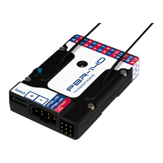
- Page 7 gned the letters A - I. As an option, you can also set the receiver outputs to generate different channel numbers. For example, the PBR-9D can be set to generate outputs 10 - 19 as well as channels 1 - 9 *. b) P²-BUS This interface is used for the external ultra-fast P²-BUS telemetry system and digital servo output.
-
Page 8: Meaning Of The Led Display
If you select this option, you can connect an additional servo to the FastTrack/ Data socket. The channel generated varies according to the type of receiver you are using. For example, if your receiver is a PBR-14D, then channel 15 is available at this socket. -
Page 9: Other Settings
All PowerBox receivers pcb´s are manufactured using the SMT method, and are therefore extremely resistant to vibration and shock. The ideal method of moun- ting the PBR-14D is to use the retaining plate supplied in the set. However, it can also be secured to any firm surface using double-sided adhesive tape. -
Page 10: Notes On Operation
You can find a detailed description of the iGyro’s features in the instructions sup- plied with the iGyro SAT. The iGyro function integrated into PowerBox receivers is completely identical to the iGyro function in our larger PowerBox systems or the iGyro3xtra. - Page 11 radio link. In order to monitor it fully, we recommend that you set up a widget at the Telemetry screen showing the LQI value, and set an alarm threshold of 60% to 70%. This ensures that any reception problem immediately triggers an alarm to make you aware of the situation.
-
Page 12: Technical Data
10. TECHNICAL DATA Frequency 2.4GHz Operating voltage 4,0V - 9,0V Number of transmitted channels 26 (at the P²-BUS interface) Number of PWM outputs Servo output resolution 4096 Steps (12Bit) Number of receive units Range (line of sight) > 9km Telemetry P²-BUS telemetry interface FastTrack interface Parameter settings from the radio... - Page 13 11. FCC This device complies with part 15 of the FCC Rules. Operation is subject to the following two conditions: (1) This device may not cause harmful interference, and (2) this device must accept any interference received, including interference that may cause undesired operation.
-
Page 14: Fcc Warning
12. IC This device contains license-exempt transmitter(s)/receiver(s) that comply with Innovation, Science and Economic Development Canada’s license-exempt RSS(s). Operation is subject to the following two conditions: (1) This device may not cause interference. (2) This device must accept any interference, including interference that may cause undesired operation of the device. - Page 15 14. IC WARNING The device has been evaluated to meet general RF exposure requirement. To maintain compliance with RSS-102 - Radio Frequency (RF) Exposure guidelines, this equipment should be installed and operated with a minimum distance of 20cm between the radiator and your body. le dispositif de a été...
-
Page 16: Set Contents
15. SET CONTENTS - PBR-14D - Mounting plate with rubber grommets and screws - Operating instructions in English and German 16. SERVICE NOTE We make every effort to provide a good service to our customers, and have now established a Support Forum which covers all queries relating to our products. -
Page 17: Service Address
We accept no liability for transit damage or loss of your shipment. If you wish to SERVICE ADDRESS make a claim under guarantee, please send the device to the following address, together PowerBox-Systems GmbH with proof of purchase and a description of Ludwig-Auer-Straße 5 the defect: 86609 Donauwoerth... - Page 18 8/2023 PowerBox-Systems GmbH Ludwig-Auer-Straße 5 86609 Donauwörth Germany +49-906-99 99 9-200 www.powerbox-systems.com...
Need help?
Do you have a question about the PBR-14D and is the answer not in the manual?
Questions and answers