Table of Contents
Advertisement
Quick Links
Advertisement
Table of Contents

Subscribe to Our Youtube Channel
Related Manuals for PowerBox Systems Core V 2.50


Summary of Contents for PowerBox Systems Core V 2.50
- Page 1 Manual 04/2021 V 2.5o www.powerbox-systems.com...
- Page 2 Dear PowerBox-Pilot, P²BUS Further advances are evident in our new bi-directional Many thanks for placing your trust in us, and purchasing our which operates as the telemetry interface, and is capable of PowerBox CORE. You have chosen an extremely unusual transferring data at unprecedented speed.
-
Page 3: Table Of Contents
Content 1. Connections, controls......4 3.10.4. Climb sensitivity ......28 3.10.5. -
Page 4: Connections, Controls
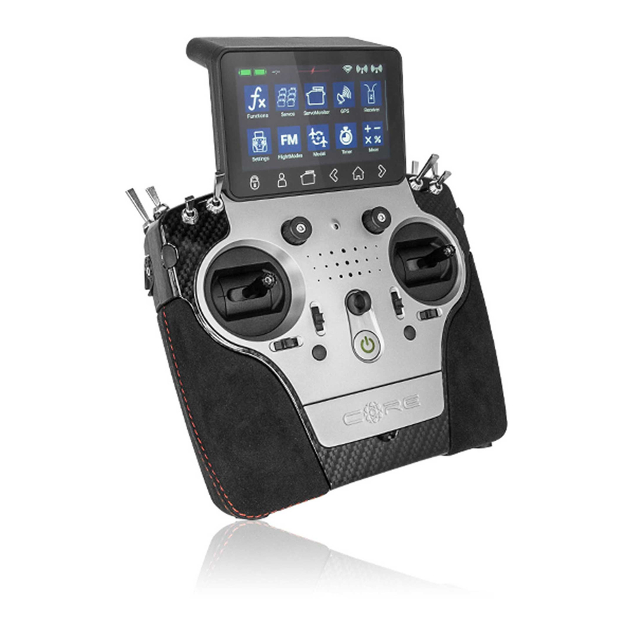
1. Connections, controls Light sensor 8 Toggle switches Quick-select buttons Optional stick switch Loudspeaker 4 proportional controls On / Off switch 4 digital trims 4 push-buttons Quick-select buttons Servo History History Screen Userdefined Home monitor back unock menu screen forward PowerBox-Systems −... -
Page 5: First Steps
2. First Steps 2.1 Switching on The CORE is switched on by holding the -Tbutton pressed in until it lights up red. Release the button briefly, then confirm the power-on process by briefly pressing the button a second time. The transmitter is switched off in exactly the same way. The button changes to green when the Linux system has booted;... -
Page 6: Main Screen
NOTE Hinweis: you can transfer any menu point to your own personal menu. This is accomplished simply by holding your finger on the appropriate menu for a few seconds. When the “Person symbol” appears, the menu point is transferred into your personal menu, which you can access conveniently using the quick-select button at the bottom of the screen. -
Page 7: Menu
Servos Servo Cut-off - Servoübersicht - Servos anlegen oder löschen 3. Menu 3. MENÜ Servo Monitor Modell - Modellübersicht 3. MENÜ Functions - Laden, kopieren oder löschen - Function overview von Modellen Mixers Flightmodes Virtual switches Funktionen Mischer - Create or erase - Funktionenübersicht functions Flight Modes... -
Page 8: Screen
• Language The Language setting affects the output of speech and telemetry data. When the sensors are scanned, the selected language is sent to the sensor, which then sends back the telemetry values using the terminology in that language - if implemented. •... -
Page 9: Audio
• Intro The Intro Video setting enables you to switch the brief CORE logo sequence on or off when the system is switched on. Disa- bling it shortens the initial boot time by a few seconds. 3.1.3. Audio The Audio menu enables you to set different volume levels. In the right-hand field you can set the volume to a fixed value. - Page 10 On the next screen you select one of the ranges on the right-hand side, e.g. Wing. The screen now shows a diagram of a wing corresponding to your chosen type. If your configuration is more specialized, that presents no problems: at a later stage you can very easily program individual functions manually.
-
Page 11: Function Menu
button, amongst the quick-select buttons at Back to our Wing screen: when all the assignments are complete, press the the bottom in order to return to the overview. You can now continue assigning transmitter controls and servos to all the remaining Continue functions. -
Page 12: Setup
• Trim Mode You can choose any of four different trim modes. The stan- dard one is Offset mode: In this mode a trim adjustment affects the entire range of stick travel, i.e. including the end-points. Alternative trim modes are Left and Right; typically, these are intended for idle adjustment in the case of engines and turbines. -
Page 13: Hold / Failsafe
• Transmitter control rate Here you can select a transmitter control which switches the rate on and off, or sets it to linear. The transmitter control can be any of the primary sticks, proportional controls or switches. • Rate Rate transmitter control. -
Page 14: Servo
3.3.6. Servo Here you will find the assigned servos again. Up to eight servos can be assigned to each function. As already mentioned in the Assistant, the travel and end-points of each servo can be adjusted separately here. Any adjustments you make to a servo at this point have no influence on the settings of the same servo if it is also assigned to another function. - Page 15 This is the procedure: use the arrow buttons to select the point you wish to adjust. Briefly press the displayed setting at Value, then adjust the servo for this position. The Smooth button can be used to even out the course of the curve. Right at the bottom you will find a Reset button which sets the curve back...
-
Page 16: Binding A Receiver
NOTE If you wish, you can reset the servo curve once you return to the Servo Overview. If you accidentally find yourself at the Reset button, that is not a problem: simply select the Curve Editor again, and the curve will still be present there with the settings you last selected. -
Page 17: Range Check
3.4.3. Range check The Range check function reduces the transmitter’s output power, thereby simulating a large distance between transmitter and model. This enables you to determine any possible weaknesses in reception in the receivers. In range check mode all the con- trols should work perfectly at a range of at least 50 m. -
Page 18: Flight Mode
You can create a new mixer by selecting the Mixer menu and pressing +. You can also immediately rename the Mixer to your own choice by touching the Mixer button. Press the Setup button on the right in order to program the mixer. The following display appears: 3.5.1. -
Page 19: Virtual Switches
• Value Move the point up or down by altering the percentage value. • Smooth The Smooth option can be used to even out the curve, thereby causing the servo to move smoothly over its travel. • Raw Raw eliminates curve smoothing. •... -
Page 20: Servo Cut-Off
Yet another option is to use the output of a previously defined logical switch in turn as a transmitter control input. In this way you can set up a logical link between three or more switches! In this example a linear rotary control has been selected. In the following section you will see your transmitter control on the left, and a bar display on the right showing two switching points. - Page 21 transmitter control First select a by briefly pressing the blank field (three dashes) under Control; press Control again at the next screen. You can now select a switch or linear control as transmitter control by operating it. Yet another option is to use the output of a previously defined logical switch in turn as a transmitter control input.
-
Page 22: Flightmodes
This adaptability provides maximum flexibility and simplicity, and you can immediately check the effect of your settings by using the linear control. The transmitter control symbol on the left changes color to indicate the switched state. If you wish to use a switch, you can very easily set the desired switch position to ON. If you select a 3-position switch it is also Cut-Off possible to set two positions. - Page 23 Before you set up flight modes it is worthwhile considering which flight modes are important, and which are of secondary importance. To create a flight mode, press briefly on one of the boxes label- led “Standard”, and you will see the following screen display: You can immediately assign an informative name to the new flight mode by briefly pressing the left-hand field.
-
Page 24: Speech Output
When you have set up multiple flight modes, you will see green dashes in the Flight Mode tree which indicate which flight mode is currently active. You can now select various settings for the different flight modes in the Transmitter Control, Trim and Mixer menus after selecting the Single setting at Flight Mode. -
Page 25: Value
• Text At the Text option you can enter any text, which is then spoken by the TTS system, for example, by a switch. • Telemetry short The selected telemetry value is spoken together with its unit. The message can be triggered by switch activation, at regular intervals, or by a change in the value. -
Page 26: Control
• Timer Select here what timer value should be spoken. Additional to that you can set if intermediate time or elapsed time should be announced. 3.9.3. Control transmitter control At this point you can select a for activa- ting the speech output, or select permanently ON/OFF. 3.9.4. -
Page 27: Test
Once option is used if you wish to have a timer or a tele- metry value spoken when a switch is operated. Interval option is used to set a fixed time after which the output is to be spoken at regular intervals. Value change option is only available if a telemetry value has been selected as source. -
Page 28: Vario On/Off
3.10.2. Vario ON/OFF At this point you can choose a transmitter control which switches the Vario tone on and off. 3.10.3. Start tone Here you determine the basic frequency of the tone output when the Vario is generating 0 m/s. 3.10.4. -
Page 29: Single Mode
The transmitter control can be either a switch or a linear control. In both cases you can set the desired switching points and the switching direction. Please note that the green range covers the sequencer running forward, the red range the reverse range. - Page 30 Now select all the servos which are to be included in the sequence; up to six servos can be selected. NOTE The servos you select at this point no longer appear in the servos available for functions! Setup At the Overview screen press to set the travel points.
- Page 31 As you can see in the above illustrations, as standard the sequencer simply runs from the Start point at -20% to the Stop point at +20%. To insert an additional point, press on the graph, then on Addition. Servo 10-Forward sequence.
-
Page 32: File Manager
A further interesting application for the sequencer would be any kind of brake flaps, spoilers or landing flaps. You know what happens: the spoiler retracts, and the servo buzzes a little because there is a slight residual mechanical resistance. Use the se- quencer to move the spoilers slowly in the usual way, but set them to run past the retracted point by about 5%, then immediately back again;... -
Page 33: Teacher/Student System
It is also possible to erase files – but caution: if you wish, for example, to erase a sound file for a telemetry alarm, then that alarm will no longer function! Even though you can quickly copy the files back into the transmitter, you may well find yourself wasting a lot of time searching for the cause of the error. - Page 34 The next step is to assign a pair of transmitter controls by pressing the symbol at Core transmitter control. Here you can as- sign one of the Student’s transmitter controls to a transmitter control at the Teacher transmitter. If you operate the switch assigned in this way, the control signals from the Student transmitter replace the transmitter control from the Teacher transmitter.
-
Page 35: Telemetry, Timers, Servo Display, Notes And Quick-Select-Buttons
In use In the field under you can remove assigned channels whose control you don’t want to transfer. This allows you to assign the complete model to the Student transmitter, but include only specific functions when control is transferred to the Student pilot - according to the Student’s skill level. -
Page 36: Telemetry
4.1 Telemetry This can be used to display all the sensors connected to the P²BUS, and show the data they generate. This information also includes the receiver and transmitter data. Technical information: The PowerBox CORE telemetry system and the P²-BUS are designed in such a way that each sensor supplies its own informa- tion, including sensor name, unit, number of sensor values, decimal point, priority and other data. -
Page 37: Sensor
The left-hand column shows all the connected sensors, while the right-hand column shows all the values which these sensors supply. The P²BUS is an in-house development, and is capable of transmitting up to 255 sensors each with 32 individual values –... -
Page 38: Menu
4.1.6. Menu The Telemetry menu is an important function, since it enables you to configure and set up sensors and other devices which are connected to the P²BUS. An example of this is the iGyro SAT, which can be connected to PBR receivers. The receiver’s Setup menu can be called up by pressing the Menu button at the corresponding sensor. -
Page 39: Value
• Sensor Rescan Now connect the next sensor, and carry out another process. Press to accept the second sensor into the system. • - Proceed as before if more sensors of the same type are to be connected. 4.1.8. Value In the column below Value, you will see the name of the sensor value. -
Page 40: Alarm
4.1.9. Alarm After the individual sensor values you will see the Alarm button. In the Alarm menu you can set a maximum of four alarm thres- green holds: one yellow alarm and one red alarm for each direction. Starting from the area in the middle, in which there is no alarm, you can set an alarm in the two left-hand... -
Page 41: Erase
4.1.10. Erase The last button (cross symbol) in the Sensor Overview can be used to erase individual telemetry values from the widget. Once you have entered all the settings, press at the bottom of the screen. 4.2 Timer CORE Timer allows you to set up eight different, independent timers. - Page 42 NOTE If you want the timer to start once, and continue running until it is reset, you do not need to assign a transmitter control to Stop. If the timer is required to start and stop alternately using a single transmitter control, simply set the same transmitter control for Stop as you set for Start, then reverse the switching points.
-
Page 43: Servo Display
4.3 Servo display This widget can show the servo output position. An useful display for flaps or gyro gain. 4.4 Quick select menu This widget type can give you a quick entry in menus which are used frequently. www.powerbox-systems.com... -
Page 44: Notes
4.5 Notes You can make text notes here – for example for pre-flight checks or any other important things. 4.6 Minimum- and Maximum display Another important feature relating to telemetry data: the CORE automatically records the maximum and minimum values for the incoming data. -
Page 45: Update
5. Update 5.1 CORE The CORE transmitter can be updated using either a USB memory stick (1GB – 32GB) or WiFi. 5.1.1. USB Update If you wish to update the transmitter, the first step is to download the PowerBox Terminal program from our website, and install CORE Update the program on your PC or laptop. -
Page 46: Wifi Update
• Update from Version 1.0 or 1.4: Pressing Update opens a window, and the transmitter invites you to carry out a restart. Do not switch the transmitter off imme- diately!! It is essential to wait for about 20 seconds, as the files must first be copied. When this period has elapsed you can restart the transmitter, and the update will be completed automatically. -
Page 47: Wifi
Important: if a radio update - for whatever reason - should fail, that is not a problem. Right at the bottom of the Update menu you will find the Restore Firmware button. Disconnect all other bound receivers from their power supply, and re-connect the Restore Firmware. -
Page 48: Charging The Transmitter
All passwords are stored in encoded form in the transmit- ter’s Linux computer memory, and cannot be read out. The Forget purpose of the button is to erase this information. Por- At the bottom right you will find two input fields for the login. -
Page 49: Connections
8. Connections Under the flap you will find additional sockets: Headphone Charge status Charging socket USB-A socket Mikrophone input Micro USB Servo/PPM socket (10-16V) socket • Headphone socket You can connect stereo headphones to this socket for spoken Vario and telemetry messages. •... - Page 50 • Opening the transmitter As standard the CORE is supplied in the correct mode, as specified by the customer, but some users may find that the centring spring tension or the ratchet function needs to be adjusted to meet their personal preferences. The first step is to remove the handrests.
- Page 51 • Adjusting the tension of the primary stick centering springs On the screws 1 and 2, the centering spring tension can be adjusted for the respective axis. Tightening the screw further increases the spring tension. If you find it impossible to set your preferred spring tension, we can supply a range of stronger springs.
-
Page 52: Calibrating The Transmitter Controls
10. Calibrating the transmitter controls PowerBox CORE Naturally the is supplied with all functions correctly calibrated. However, if you wish to swap a switch or repla- ce a broken switch, we recommend that you re-calibrate the new switch. Re-calibration is also necessary if, for example, you limit the throttle stick travel, or change the transmitter mode mechanically. -
Page 53: Specification
11.Specification Power supply Li-Ion Channels Servo signal resolution 4096 Bit Screen TFT - Touch Weight Handheld version: 1190 g Tray version: 1330 g Temperature range -30 °C bis +85 °C 12. Set contents • PowerBox CORE • 1x PBR-9D • Case •... -
Page 54: Core Accessories
13. Core accessories RECEIVERS PBR-9D Order No. 8210 This is a nine-channel receiver with two redundant receiver circuits. The unit features P²BUS interface for servo and telemetry data, and an auxiliary output which can be configured either as SRXL bus or as channel 10. PBR-7S Order No. - Page 55 SENSORS PBS-V60 Order No. 6620 PBS-V60 is a small, lightweight voltage sensor which we have developed for use PowerBox CORE, but is also suitable for use with other telemetry systems with the currently on the market. PBS-P16 Order No. 6622 PBS-P16 is an ultra-precise pressure sensor for up to 16 Bar.
-
Page 56: Service Note
14. Service note We are anxious to offer good service to our customers, and to this end we have set up a Support Forum which deals with all queries concerning our products. This relieves us of a great deal of work, as it eliminates the need to answer frequently asked questions time and again. -
Page 57: Rf Exposure Statement (Portable Device)
18. IC This device contains license-exempt transmitter(s)/receiver(s) that comply with Innovation, Science and Economic Development Canada’s license-exempt RSS(s). Operation is subject to the following two conditions: (1) This device may not cause interference. (2) This device must accept any interference, including interference that may cause undesired operation of the device. - Page 58 PowerBox-Systems − World Leaders in RC Power Supply Systems...
- Page 59 Notizen www.powerbox-systems.com...
- Page 60 04/2021 PowerBox-Systems GmbH Ludwig-Auer-Straße 5 86609 Donauwörth Germany +49-906-99 99 9-200 +49-906-99 99 9-209 www.powerbox-systems.com...
Need help?
Do you have a question about the Core V 2.50 and is the answer not in the manual?
Questions and answers