Table of Contents
Advertisement
Quick Links
F-Test
Pixel Tester/Data Analyzer
Owners Manual
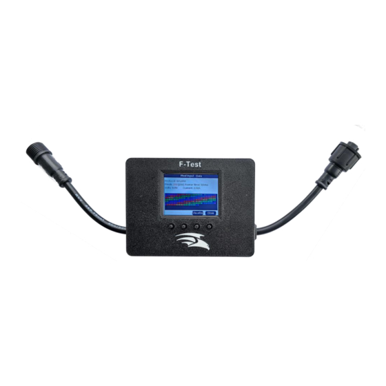
The F-Test is a small, handheld all-purpose tester/analyzer to help troubleshoot and diagnose problems in
animated lighting shows. The F-Test can help you isolate the problem to a specific component by being able to
not only send test data to pixels, receivers, etc. but to also analyze incoming WS281x, Differential data, DMX
and other common data types used in animated lighting shows.
There are many more things this hardware is capable of but has not been included in the first release because
we are unsure of demand for those features. If you have something that you would like to have the tester do
and we get enough support for the idea (or it is trivial to implement) then it may well be included in a
firmware update. Please visit
https://github.com/Pixelcontroller/f-test_issues
to lodge your request.
Page | 1
Advertisement
Table of Contents

Related Manuals for Falcon F-Test


Summary of Contents for Falcon F-Test
- Page 1 The F-Test is a small, handheld all-purpose tester/analyzer to help troubleshoot and diagnose problems in animated lighting shows. The F-Test can help you isolate the problem to a specific component by being able to not only send test data to pixels, receivers, etc. but to also analyze incoming WS281x, Differential data, DMX and other common data types used in animated lighting shows.
-
Page 2: Table Of Contents
Table of Contents Introduction ..................................3 F-Test Modes ................................... 3 F-Test Overview ................................4 Front View ................................... 4 Back View ..................................4 Side One ..................................5 Side Two ..................................5 Side Three ..................................6 Side Four ..................................6 Main Menu .................................. 7 Settings Page ................................... -
Page 3: Introduction
Adapter Cable wiring diagrams. When the F-Test is connected with both Pixel input data and to pixel strings, it will act as an F-Amp and clean the signal. This can be useful to determine if an F-Amp would help in your situation. -
Page 4: F-Test Overview
F-Test Overview Front View 1. xConnect Pixel Data Input 2. Navigation Buttons (function will vary depending on the active screen) 3. xConnect Pixel Data output Back View Page | 4... -
Page 5: Side One
Side One 1. USB Power jack. The F-Test requires some sort of power. If connected to an energized pixel string, this will supply the power needed. If you do not have an energized pixel string connected to the F-Test, then you can supply power through the USB port. -
Page 6: Side Three
Side Three 1. Micro SD Card slot. This is used for firmware updates when needed and for logging if selected. Side Four 1. Smart Remote Output port. This port is used to output Smart Remote data to Smart Remote to see if they are functioning correctly. -
Page 7: Main Menu
Main Menu When the F-Test is powered on, it will boot up to the Main Menu unless you have configured it to default to another menu Item 1. Navigation Buttons- These buttons are used to navigate through the different menu items. The function of each button is labeled above the button. -
Page 8: Settings Page
Settings Page The settings page is used to configure your F-Test. Pressing the Up and Down buttons will navigate through the available options in the highlighted menu item. The Next button will move the highlighted selection to the next item in the Menu. The close button will take you back to the Main Menu. - Page 9 Multi Strobe Blink Rainbow Chase White Chase Color Chase Random Chase Rainbow Chase Flash Chase Flash Random Chase Rainbow White Chase Blackout Chase Blackout Rainbow Color Sweep Random Running Color Running Red Blue Running Random Larson Scanner Comet Fireworks Fireworks Random Merry Christmas Fire Flicker Fire Flicker Soft...
-
Page 10: Save Settings Page
Save Settings Page When you save your settings, F-Test does not just save the settings on the settings page, it also saves all the settings on all the pages to be the default settings when those pages open. For example ... if you want to set a default test pattern when testing pixels then go to pixel out, choose your test pattern then go back and select save settings. - Page 11 F-Test). If the F-Test is receiving data while in this mode, the tester will suppress that pixel data and override it with the selected test pattern. When outputting data, the tester sends data for the number of pixels you configured in the Pixel Output page, regardless of how many are attached.
-
Page 12: Smart Receiver Out
Note: The F-Test will have to have a power supply attached, either through the USB port or the Pixel Input. Pressing the Up and Down buttons will navigate through the available options in the highlighted menu item. The Next button will move the highlighted selection to the next item in the Menu. -
Page 13: Dmx Out
F-Test will connect to the first receiver and have the dial set to A and the terminators all off. This is then connected to the second receiver and the Dial set to B with the terminators all on. Set the F-Test Brand to FPP V2 and then the Receiver to All and then Pattern to A. -
Page 14: Monitoring Mode
3 channel and in RGB color order. If it isn’t it may display different colors or look quite different to the actual pixels. In this mode, the F-Test will also act like an F-Amp and could be helpful in determining if an F-Amp would be beneficial. -
Page 15: Data
Pressing the Visualize button will navigate through the various view options. The close button will take you back to the Main Menu. The screen displays the following data: Protocol- Only WS2811 and compatible pixels are supported. Pixels - There are 2 numbers displayed for each port. The first is the number of pixels worth of data the tester is receiving on the data line. -
Page 16: Brightness
Brightness- This will give you a graphical representation of the overall brightness of your pixels averaged over time by RGB color order. Volts/Current- This plots over time the input voltage on a scale of 0-15V and the output current draw on a scale of 0-5 Amps. -
Page 17: Oscilloscope
Oscilloscope- This screen is useful to both see that a data signal is present but also see that data voltage. The pink line shows the typical minimum voltage required for a pixel to interpret the data. If the waveform displayed is not displaying above this pink line, then you probably have a weak signal that will need to be remedied. - Page 18 Note: The F-Test will need to have a power supply attached, either through the USB port or the Pixel Input.
-
Page 19: Data
inconsistent with what you might expect. This happens if the last pixels on your prop are turned black. The tester will also indicate if it suspects torn frames by displaying the pixel count in red. This should be ignored most of the time but if you are running color fades and the like it can tell you if the controller is keeping up with your data stream. -
Page 20: Dmx In
DMX device’s behavior. Note: The F-Test will need to have a power supply attached, either through the USB port or the Pixel Input. Pressing the Up and Down buttons will navigate through the available options in the highlighted menu item. The Next button will move the highlighted selection to the next item in the Menu. -
Page 21: Brightness
Brightness- This shows the average of all channels over time. Data Bars- This view shows the channel data over several pages (use up/down to move between them) as a column chart where the height of the column represents the channel value. The number to the bottom left of the chart is the number of the first channel being displayed on this page. -
Page 22: Values
Values- This view shows the actual channel values over several pages (use up/down to move between them). If this page is blank it is because no data is being received. Page | 22... -
Page 23: Reference
Reference The reference page provides diagrams of Pinout diagrams for several different connectors: Ray Wu- This shows the typical male and female pinouts of an Ray Wu pigtail. xConnect- This shows the typical male and female pinouts of an xConnect pigtail. Page | 23... - Page 24 DMX XLR-T568A- This shows the wiring to connect a RJ45 jack that would connect into a controller to a DMX fixture using a SLR male or female plug. Renard Adapter- This shows the cat-5 cable that you need to connect a Renard controller to a falcons DMX RJ45 connector.
-
Page 25: Troubleshooting Practices
With the F-Test still connected, go to the Pixel Input function and see if you are getting data there, if you are, then you know the problem is on the connector itself.
Need help?
Do you have a question about the F-Test and is the answer not in the manual?
Questions and answers