Advertisement
Quick Links
Installation guide and user manual for the stair controller
Contents
I.
Contents of your set ........................................................................................................................ 2
II.
Equipment required for installation ................................................................................................ 3
III.
Safety notices .............................................................................................................................. 3
DIY tips and safety advice .................................................................................................................... 3
Electrical work safety advice and tips ................................................................................................. 3
IV.
Installation guide ......................................................................................................................... 4
V.
Setting the controller .................................................................................................................... 12
VI.
Troubleshooting guide .............................................................................................................. 18
These motion sensor-activated LED stair lights switch on automatically to light up your stairs when
you reach the top or bottom step.
Control unit SCR2 switches each step individually, giving a sweeping motion up or down the staircase,
then turns off the lights together, by gently fading out.
This document explains how to install and operate your control unit.
Page 1 of 19
SCR-2
Advertisement

Related Manuals for Stellar Lighting SCR-2


Summary of Contents for Stellar Lighting SCR-2
-
Page 1: Table Of Contents
Installation guide and user manual for the stair controller SCR-2 Contents Contents of your set ........................2 Equipment required for installation ....................3 III. Safety notices ..........................3 DIY tips and safety advice ........................3 Electrical work safety advice and tips ....................3 Installation guide ......................... -
Page 2: Contents Of Your Set
Contents of your set Your minimum set includes: • The controller with a touch panel • Screw terminal blocks • Motion sensors (with 10m three-core wire) Optional contents (depending on set purchased): • LED stair lighting strips with 1 m two-core wire tails and aluminium profile, end caps and diffuser for each light strip, or •... -
Page 3: Equipment Required For Installation
Equipment required for installation You will need: • Screws suitable for your installation and stair lighting configuration • Adhesive tape or glue to attach motion sensors • 2 x 0.3 mm2 or 2 x 0.75 mm2 wire as required to extend the tails on the stair strips •... -
Page 4: Installation Guide
• Our recommended LED light strip: SMD 3528 60LED/m with 4,8W/m • Cascading (SCR-2) controller: 2-20 lights, 9.6 W per light. o DO NOT EXCEED 180 cm length per output with these LED strips (SMD 3528 60 LED/m) Before starting the installation, please check the contents of the box to make sure all components are there and read these instructions in full. - Page 5 Decide on the location for your control unit and power supply. Both are designed to fit on a DIN rail (optional) for ease of installation. Choose the instruction that matches your lights. a) LED strip lights with profiles: Attach the profile to the stairs, according to your chosen profile.
- Page 6 b) Mini spotlights: The spotlights are suitable for flush-mounted installation Mini spotlight dimensions Connection diagram for mini spotlights Page 6 of 19...
- Page 7 c) Surface-mounted/ Flush-mounted spotlights: The spotlights are suitable for surface-mounted and flush-mounted installation The surface-mounted frame can be removed if the lights are flush-mounted. The dimensions of the surface or flush-mounted can be seen on the diagrams below. Surface-mounted Flush-mounted 3) Position the motion sensors at the top and bottom of the stairs so that the person entering the staircase crosses the beam.
- Page 8 remains uncovered so the beam can operate properly. Dimensions: ● Diameter 4cm, thickness 1.4cm Motion sensors are interchangeable so it doesn’t matter which goes at the top and bottom of the stairs. We provide 10 m of cable with each motion sensor, giving you flexibility on how you install your stair lights.
- Page 9 This action must be performed whilst the unit is disconnected from the power supply! OPTIONAL: If the stair lighting set is connected to the switch on the wall (remember that for the set to function properly it must be a bell switch (also known as momentary switch or push switch), connect it in the place indicated in the photo below.
- Page 10 • terminals on the control unit are located on the top left, labelled + and - • terminals on the power supply unit are located on the top right, labelled V+ and V-. There are two sets of terminals; only one V+ and one V- should be used 6) To test your installation, you need to connect one light to the control unit.
- Page 11 TIP: For this purpose, it is best to use a 2x0.3mm2 or 2x0.75mm2 stranded cable. 7) Connect the power supply unit to the mains, according to the diagram on the unit. 8) Check the motion sensor activates correctly. There are 10 LED indicators at the top of the controller: •...
-
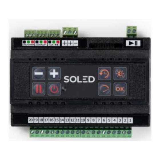
Page 12: Setting The Controller
Setting the controller Your control unit has the following buttons: Reduce / increase Brightness Duration setting Pause Accept Speed On/Off On/Off: Turns the power on the control unit on or off. Pause: Removes motion sensor control so the lights are on continuously. Function buttons: Brightness: use this button to set the maximum brightness for your lights. - Page 13 TIP: Both lighting speed and lighting time are related to brightness. The easiest way to set the driver is to set the brightness at the beginning and then the rest of the parameters. 12) Setting the number of steps To set the number of steps, reset the controller as follows: •...
- Page 14 We are now in step number setting mode. • To increase the number of required steps, press the "+" button, each pressing will increase the value by 1 stair (at the same time the arrangement of the information diodes will change), use the "-" button to decrease the value of the degrees. •...
- Page 15 Brightness adjustment • The controller must be connected to the motion sensors, step lights and the power supply and powered on. • When setting the brightness, the indicator LED number 5 should be on. • After pressing the "Brightness adjustment" button, set a specific value using the "+" and "-" buttons and then confirm the changes by pressing OK.
- Page 16 14) Duration settings • The controller must be connected to the motion sensors, step lights and the power supply and powered on. • When setting the lighting time, the diode number 6 should be on. • After pressing the “Duration” button, set a specific value using the "+" and "-" buttons and then confirm the changes by pressing OK.
- Page 17 Speed Slowest ✔ ✔ ✔ ✔ ✔ ✔ ✔ ✔ ✔ ✔ ✔ ✔ Fastest Page 17 of 19...
-
Page 18: Troubleshooting Guide
Troubleshooting guide If your set is not behaving in the way you expect, please consult the following troubleshooting tips for information that may resolve the issue. LED strips: Issue Troubleshooting steps Further action An LED strip is not Find out if the issue is with the LED strip or the If the issue is with the working or its controller slot:... - Page 19 Timer is not working Refer to the Timer manual’s wiring diagram and operating instructions. If the above steps don’t resolve the problem, please contact Stellar Lighting Ltd., by sending an email info@stellarlighting.co.uk with the following content: ● Your order reference number, ●...
Need help?
Do you have a question about the SCR-2 and is the answer not in the manual?
Questions and answers