Table of Contents
Advertisement
Quick Links
Instruction Manual of
DJS5179 Electronic DC Energy Meter
Technology consultation: 0816-2280829
Quality compliant: 0816-2278273
Sales tel: 0816-2278150/1/2/3/4
Sales fax: 0816-2281934
Executive standard: GB/T29318-2012
Address: No.98 Youxian East, Youxian District, Mianyang, Sichuan,
China
Code no.: 621000
E-mail: wbwm@wbdz.cn
http://www.wbsensor.com
Advertisement
Table of Contents

Related Manuals for Mianyang Weibo Electronic DJS5179


Summary of Contents for Mianyang Weibo Electronic DJS5179
- Page 1 Instruction Manual of DJS5179 Electronic DC Energy Meter Technology consultation: 0816-2280829 Quality compliant: 0816-2278273 Sales tel: 0816-2278150/1/2/3/4 Sales fax: 0816-2281934 Executive standard: GB/T29318-2012 Address: No.98 Youxian East, Youxian District, Mianyang, Sichuan, China Code no.: 621000 E-mail: wbwm@wbdz.cn http://www.wbsensor.com...
- Page 2 DJS5179 Preface Thank you for choosing DJS5179 Electronic DC Energy Meter. We hope that this product can bring you a pleasant application experience. If the package or product appearance is damaged when you receive the product, please contact us or your supplier immediately.
-
Page 3: Table Of Contents
DJS5179 Catalogue 1.Safety usage instructions ....................... 1 2. Product introduction ......................2 2.1Summary ............................2 2.2Product features ..........................2 3 Structural features and operating principle ................ 3 4 Key technical parameters ...................... 3 4.1 Key technical parameters ........................ 3 4.2 Pulse Output ............................. 4 5 Outline dimension ........................ - Page 4 DJS5169 9 After sales service ......................... 45 9.1 New product quality assurance..................... 45 9.2 Product warranty limit ........................45 10 Package, transportation and storage ................46 10.1 Storage ............................46 10.2 Transportation and storage ......................46 Complimentary clause ......................46...
-
Page 5: Safety Usage Instructions
DJS5179 1.Safety usage instructions This instruction manual is used to describe DJS5169 DC Energy Meter. Please read this instruction manual carefully before installing, operating and maintaining this product. You are supposed to have basic knowledge in electrical engineering area by this instruction manual. -
Page 6: Product Introduction
2. Product introduction 2.1Summary DJS5179 Electronic DC Energy Meter is a new generation of programmable intelligent instrument. The instrument supports DC signal monitoring of two channels voltage and two channels current. It can be widely applied to DC signal equipment such as DC charging pile and DC power supply. -
Page 7: Structural Features And Operating Principle
DJS5179 ● 2 channel electric energy pulse output, 1 channel second pulse output. 3 Structural features and operating principle The structure of the instrument adopts modular structure design and optional auxiliary power functions. The instrument adopts guide rail structure design, which is suitable for NS35/7.5, NS35/15 or European EN50022 standard guide rails. -
Page 8: Pulse Output
DJS5179 Operating temperature -25℃~+55℃ Ambient Limit operating temperature -40℃~+70℃ temperature Storage temperature -40℃~+70℃ Relative humidity 5%~95%, no condensation and corrosive gases 4.2 Pulse Output The instrument has 2 channel electric energy pulse output and 1 channel second pulse output, and the output mode is the open collector optocoupler output. The open collector voltage is VCC ≤... -
Page 9: Installation And Usage
DJS5179 6 Installation and usage 6.1 Installation method The instrument is lead rail mounted and the width of the lead rail is 35mm. 6.2 Installation precautions ● The product shall be installed in a dry, well ventilated place away from heat and strong electricity (magnetic) fields. - Page 10 DJS5179 Figure 2 Outline of the instrument Table 2 Wiring terminals definition Function code Description Power supply positive terminal Power supply ground terminal RS485communication interface terminal A RS485communication interface terminal B Positive voltage output of Circuit 1 Negative voltage output of Circuit 1...
-
Page 11: Power Supply Wiring
DJS5179 Negative voltage output of Circuit 2 mV Positive current input of Circuit 2 mV Negative current input of Circuit 2 Positive pulse output of Circuit 1 Negative pulse output of Circuit 1 Positive pulse output of Circuit 2 Negative pulse output of Circuit 2... -
Page 12: Energy Pulse Output Wiring
DJS5179 Shunt negative input(X=1,2) Figure 5 Input signals wiring Warning ● The rated input voltage shall not be higher than the rated input voltage of the equipment; terminal block is recommended in consideration of maintenance and 1A fuse is recommended in the voltage input terminal of the instrument;... -
Page 13: Usage
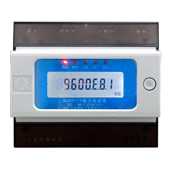
DJS5179 6.4 Usage 6.4.1Panel description Displaying panel is seen in Figure 7. Displaying panel description is seen in Table 3. Figure 7 Displaying panel Table 3 Displaying panel description Identification Description Product operating indicator light Communication receiving indicator light Communication sending indicator light... -
Page 14: Lcd Display Description
DJS51 6.5.2 LCD D display de escription display des cription is s seen in Figu ure 4. Figur e 4 Display c content Item splay content on LCD Description Full scre Full screen dis splay on LCD indicates circuit 1, indicates ircuit 2 Data in high le... - Page 15 DJS51 Figur e 6 Display c content Display ite on the LCD di i splay conten Descripti Note name(Un screen Voltage in cir rcuit 1 Vol ltage ircuit Current in cir rcuit 1 rrent in circui it 1: 300A Power in cir rcuit 1 Pow ircuit kWh)
- Page 16 DJS51 bites itive electric energy in high level Positive electric circ cuit 2: 36kWh energy in cir rcuit 2 as both in high and bites kWh) wer levels are displayed low level + 4 cycl le automatica ally bites decimals bites gative electri ic energy...
-
Page 17: Communication Protocol
DJS51 ud rate: 9600; Baud rate 、 rification mo ode: even verification m mode、 rification; data bite (bit) a bite: 8bit; stop bite(b bit) 、 Stop p bite: 1bit ant in Puls se constant in circuit Pulse consta circuit 1 1:... -
Page 18: Modbus-Rtu Protocol
DJS5179 7.1 MODBUS-RTU protocol 7.1.1Summary The MODBUS protocol uses a master-slave response mode of communication connection on a communication line. First, the signal of the host computer is addressed to a terminal device (slave) with a unique address, and then the response signal from the terminal device is transmitted to the host in the opposite direction, i.e., the signal along a separate communication line The opposite... -
Page 19: Function Code Description
DJS5179 with the RTU mode of the MODBUS protocol. Each data frame includes 1 start bit, 1 function bit, 8 data bits, (parity bit), 1 stop bit (when there is a check), 2 stop bits (when there is no check). The structure of the data frame: that is, the message format. -
Page 20: Abnormal Response
DJS5179 table lists the function codes, their meaning and function supported by the meter. Code Meaning Action 0x03 Read data register Get one or more register values inside the current meter 0x05 Switching output control Controls a relay inside the current meter... -
Page 21: Example Of Communication Messages
DJS5179 returned by the slave to the host is based on the function code sent by the host. 128. The format of the error message returned by the slave is as follows: Address Function code (highest CRC check code low... - Page 22 DJS5179 Channel address 2 bytes Channel address 2 bytes Control instruction 2 bytes Control instruction 2 bytes CRC check code 2 bytes CRC check code 2 bytes Remark: Channel address: 7000; Control command: 0xFF00 control relay is closed, 0x0000 control relay is released.
-
Page 23: Parameter Register Table
DJS5179 password) password password 03H 84H 08H 16H xxHxxH xxHxxH 7.1.5 Parameter Register Table The instrument has excellent programmability. The parameters of the specific configuration are shown in Table 7. Before the instrument is officially used, we recommend that the user configure it according to actual needs. - Page 24 DJS5179 valley 6012 Period 3 time Time 13:00 1:sharp;2:peak;3:flat;4: 6013 Period 3 rate no. valley 6014 Period 4 time Time 19:00 1:sharp;2:peak;3:flat;4: 6015 Period 4 rate no. valley Pulse constant in 6016 See note 1 circuit 1 Pulse constant in...
- Page 25 DJS5179 6034 0:00 Period 12 time Time 1:sharp;2:peak;3:flat;4: 6035 Period 12 rate no. valley 6036 0:00 Period 13 time Time 1:sharp;2:peak;3:flat;4: 6037 Period 13 rate no. valley 6038 0:00 Period 14 time Time 1:sharp;2:peak;3:flat;4: 6039 Period 14 rate no. valley...
- Page 26 DJS5179 Low power of circuit 2 INT32 0.1W High power of circuit 2 Positive low energy of circuit 1 UINT32 0.01kWh Positive high energy of circuit 1 Positive low energy of circuit 2 UINT32 0.01kWh Negative high energy of circuit 2...
- Page 27 DJS5179 1002 1003 Hour 1004 Minute 1005 Second 1006 Week Table 11 Event Record Data Register Table Data Register Name Description classification 1200 Total power down times UINT16 Bit0:Fram hardware failure;Bit1: Flash hardware failure;Bit2:battery 1201 Fault alarm UINT16 voltage shortage alarm。1indicats for alarm,0 indicates for normal.
- Page 28 DJS5179 max. max. value value times record Clearing 1:clear dataof circuit 1; 1212 max. value UINT16 2:clear dataof circuit 2; mode 3:clear all data. Year、 1213 UINT16 month 1214 Day、hour UINT16 Time of last clearing energy Min.、 1215 UINT16 Second...
- Page 29 DJS5179 circuit 1 Positive high energy in Apr. 2011 of circuit 1 Positive low energy in May of 2012 circuit 1 UINT32 0.01kWh Positive high energy in May 2013 of circuit 1 Positive low energy in Jun. of 2014 circuit 1 UINT32 0.01kWh...
- Page 30 DJS5179 Positive high energy in Dec. 2027 of circuit 1 Negative low energy in Jan. of 2028 circuit 1 UINT32 0.01kWh Negative high energy in Jan. 2029 of circuit 1 Negative low energy in Feb. 2030 of circuit 1 UINT32 0.01kWh...
- Page 31 DJS5179 of circuit 1 Negative low energy in Sep. 2044 of circuit 1 UINT32 0.01kWh Negative high energy in Sep. 2045 of circuit 1 Negative low energy in Oct. 2046 of circuit 1 UINT32 0.01kWh Negative high energy in Oct.
- Page 32 DJS5179 Negative low energy of circuit 2060 UINT32 0.01kWh Negative high energy of 2061 circuit 1 Negative low energy of circuit 2062 UINT32 0.01kWh Negative high energy of 2063 circuit 1 Negative low energy of 2064 circuit 1 UINT32 0.01kWh...
- Page 33 DJS5179 circuit 1 in Jan. Positive electronic energy 49-64 bites of 8011 circuit 1 in Jan. Positive electronic energy 1-16 bites of 8012 circuit 1 in Feb. Positive electronic energy 17-32 bites of 8013 circuit 1 in Feb. UINT64 0.0001kWh...
- Page 34 DJS5179 circuit 1 in Aug. Positive electronic energy 33-48 bites of 8038 circuit 1 in Aug. Positive electronic energy 49-64 bites of 8039 circuit 1 in Aug. Positive electronic energy 1-16 bites of 8040 circuit 1 in Sep. Positive electronic energy 17-32 bites of 8041 circuit 1 in Sep.
-
Page 35: Dl/T645-2007 Protocol
DJS5179 bites of circuit 1 Positive peak electronic energy 49-64 8111 bites of circuit 1 Positive flat electronic energy 1-16 bites 8112 of circuit 1 Positive flat electronic energy 17-32 8113 bites of circuit 1 UINT64 0.0001kWh Positive flat electronic energy 33-48... -
Page 36: Frame Format
DJS5179 7.2.2 Frame format The establishment and cancellation of the communication link are controlled by the information frame sent by the primary station. Each frame consists of a frame start character, a slave address field, a control code, a data field length, a data field, a frame information vertical check code, and a frame end character. -
Page 37: 3Data Identification
DJS5179 Figure 9Control code format The length L of the data field is the number of bytes, L ≤ 200 when reading data, L ≤ 50 when writing data, and L = 0 indicates no data field. The data field includes data identification, password, operator code, data, frame number, etc., and its structure changes with the function of the... - Page 38 DJS5179 Table 15 Basic registers Data Identification Name Data format length Unit Address code (byte) Voltage of circuit 1 xxx.x Addr 0x02010100 Voltage of circuit 2 xxx.x Addr+1 0x02010100 Voltage data block xxx.x Addr/Addr+1 0x0201ff00 Current of circuit 1 xxx.xxx...
- Page 39 DJS5179 Data Identification Name Data format length Unit Address code (byte) Total power down NNNNNN time Addr/Addr+1 0x03110000 times Addr/ Hardware failure NNNN 0x03301002 Addr+1 Addr/ Checking time times NNNNNN time 0x03300400 Addr+1 Addr/ Time of last Checking Addr+1 YYMMDDhhmmss...
- Page 40 DJS5179 The 1 positive active xxxxxx.xx Addr 0x00010300 flat energyof circuit 1 The 1 positive active valley energyof circuit xxxxxx.xx Addr 0x00010400 Positive energy data xxxxxx.xx block for 4 timesof sharp peak flat Addr 0x0001ff00 circuit 1 valley xxxxxx.xx Energy data block from Jan.
- Page 41 DJS5179 Max. power value xx.xxxxYYNNDDhhmmss Addr 0x03101003 timeof circuit 1 Max. voltage xxx.x value and time Addr+1 0x03101001 of circuit 2 YYNNDDhhmmss Max. current value and time xxx.xxxYYNNDDhhmmss Addr+1 0x03101002 of circuit 2 Max. power value and time xx.xxxxYYNNDDhhmmss Addr+1...
- Page 42 DJS5179 Hour minute 0x14 Hhmmss Addr/Addr+1 0x04000102 second Hour、minute、 no. of period 1 HHmmNN 0x14 …… …… Addr/Addr+1 0x04010001 Hour、minute、 HHmmNN no. of period 4 Automatic 0x14 NNNN Addr/Addr+1 0x04000109 reading day Pulse constant 0x14 NNNNNN imp/kwh Addr 0x04000409 of circuit 1...
-
Page 43: 4Communication Packet Description
DJS5179 Clearing max. 0x1b value command Addr of circuit 1 Clearing max. value 0x1b Addr+1 commandof circuit 2 Remarks: 1. Addr is the set meter address; 2. Refer to Table 6 for the configuration range of configuration data. 3. All the power data read by the communication are secondary values (except for the electric energy), and there is no conversion ratio. - Page 44 DJS5179 Slave normal response Control code: C=D1H Data field length: L=01H Frame format: Error information ERR 7.2.4.2 Broadcast time checking Function: Force time synchronization between slave and master. Control code: C=08H Data field length: L=06H Data field: YYMMDDhhmmss(Year、month、day、hour、minute、second) Frame format: Note: 1、...
- Page 45 DJS5179 7.2.4.3 Writing data Host request frame Function: The host requests the setup data from the slave Function code: C=14H Code field length: L=04H+04H(password)+04H(operator code)+m(data length) Data field: DI +PAP0P1P2+C0C1C2C3+DATA Frame format: Slave normal response Control code: C=94H Data field length: L=00H...
- Page 46 DJS5179 Frame format: Slave normal response Control code: C=95H Address field: A0A1A2A3A4A5 new setting communication address Data field length: L=00H Frame format: No response for slave abnormal situation 7.2.4.5 Communication baud rate Host request frame Function: current communication rate is changed to other standard rate.
- Page 47 DJS5179 Communication rate characteristic word 7.2.4.6 Modifying password Host request frame Function: modifying slave password Note: 0 indicates non-current interface communication rate, 1 indicates current interface communication rate and characteristic word is only effective when one of the Bites is 1.
- Page 48 DJS5179 Host request frame Function: empty electricity of energy meter Function code: C=1aH Data field length: L=08H Data field: PAP0P1P2+ C0C1C2C3 Frame format: Slave normal response Control code: C=9AH Data field length: L=00H Frame format: Slave abnormal response Control code: C=DAH Data field length: L=01H Note: all PAP0P1P2 are 0,all C0C1C2C3 are 0...
-
Page 49: Note
DJS5179 Control code: C=9BH Data field length: L=00H Frame format: Slave abnormal response Control code: C=DBH Data field length: L=01H Note: all PAP0P1P2 are 0,all C0C1C2C3 are 0. 8 Note a) The product needs to be warmed up for 5 minutes after it is powered on. - Page 50 DJS5179 ● Damage caused by improper installation, usage and storage; ● Exceeding the abnormal operation and application conditions regulated by the product; ● Products which have been repaired not by the company or not by an organization or person authorized by the company;...
Need help?
Do you have a question about the DJS5179 and is the answer not in the manual?
Questions and answers