Table of Contents
Advertisement
Quick Links
Advertisement
Table of Contents

Related Manuals for Siargo MFC2000 Series

Summary of Contents for Siargo MFC2000 Series
- Page 1 Operating manual Mass flow controller VA.0 M F C 2 0 0 0 S E R I E S...
- Page 2 3100 De La Cruz Boulevard, Suite 210 Santa Clara, CA 95054 Tel: +1(408)969.0368 Email: info@siargo.com © Copyright 2023 by Siargo Ltd. Siargo Ltd. and its subsidiaries reserve the right to change the specifications and/or descriptions without prior notice. www.SMERI.com Mass flow controller MFC2000 User Manual...
- Page 3 Attention! • Please carefully read this manual prior to operating this product. • Do not open or modify any hardware which may lead to irrecoverable damage. • Do not use this product if you suspect any malfunctions or defection. • Do not use this product for corrosive media or in a strong vibration environment.
-
Page 4: Table Of Contents
Table of Contents 1. Overview ....................5 2. Receipt / unpack of the products ..............6 3. Knowing the products ................7 3.1. Product description ....................7 3.2. Power and data cable description ................7 3.3. Mechanical dimensions ....................8 4. - Page 5 10. Warranty and Liability ................25 11. Service/order contact and other information ..........27 Appendix: Document history ................ 28 www.SMERI.com Mass flow controller MFC2000 User Manual...
-
Page 6: Overview
1. Overview This manual provides essential information for the operation of the MFC2000 series of gas mass flow controllers for non-corrosive gas flow control applications with the full-scale mass flow rate of from 50sccm up to 200 SLPM, and both analog set point or RS485 Modbus interface for the mass flow control. -
Page 7: Receipt / Unpack Of The Products
2. Receipt / unpack of the products Upon receipt of the products, please check the packing box before dismantling the packing materials. Ensure no damages during shipping. If any abnormality is observed, please contact and notify the carrier who shipped the product and inform the distributors or sales representatives if the order is not placed directly with the manufacturer, otherwise, the manufacturer should be informed as well. -
Page 8: Knowing The Products
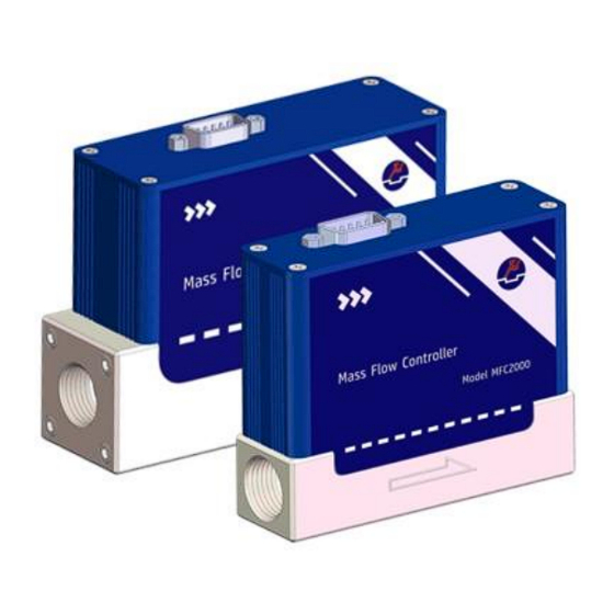
3. Knowing the products 3.1. Product description Electrical wire pin description Electrical interface Controller body Flow inlet Installation thread 4-M4x6 Flow direction Figure 3.1: MFC2000 product with DB9 interface 3.2. Power and data cable description Table 3.1: MFC2000 DB9 pin/wire assignments. Wire Color Definition... -
Page 9: Mechanical Dimensions
3.3. Mechanical dimensions Figure 3.3: MFC2000 dimensions with FNPT 1/4” connectors, for models with full-scale up to 20 SLPM; 1/8” FNPT connectors are available for flow rate less than 5SLPM, dimensions will be updated when additional models are released. Figure 3.4: MFC2000 dimensions with FNPT 3/8” connectors, for models with full-scale up to 100 SLPM. The dimensions of higher flow rate models will be updated later. -
Page 10: Installation
4. Installation Do not open or alter any part of the product which would lead to malfunction and irrecoverable damage. It will also forfeit the terms of the warranty and cause liability. Check the application requirements and verify whether they are matching to the product specifications, in particular the gas compatibility and pressure/temperature ratings for safety reasons. - Page 11 f) Make sure the power source is at the off status before connecting electrical wires per the wire definition in Table 3.1. Please be sure of the power supply range (i.e., 8 ~ 24 VDC) and power supply polarization. If an adapter is used, make sure the adapter meets industrial standards and has all safety certifications.
-
Page 12: Operation
5. Operation 5.1 Check the product specifications Before starting to use this product, check the product specifications that can be found in this manual or the basic information from the datasheet at SMERI website. The detailed product technical specifications can be found in Section 7. For a specific application, the pressure rating must not be higher than the system pressure to be measured, and the flow range should also be within the specified ones. -
Page 13: Rs485 Modbus Communication Protocol
5.4 RS485 Modbus communication protocol The digital communication protocol is based on standard Modbus RTU Half-plex mode. A master (PC or PLC) can communicate with multiple slaves (the current product) for data exchange and communication parameter configuration. Refer to Table 3.1 for the cable connection. 5.4.1 Hardware connection The RS485 hardware layer is TIA/EIA-485-A, as illustrated below. -
Page 14: Frame
5.4.3 Frame The frame function is based on the standard Modbus RTU framing: Table 5.2: frame function Start_bits Address Function codes Data Stop_bits T1-T2-T3-T4 8 bit 8 bit N 8 bit (20≥n≥0) 16 bit T1-T2-T3-T4 Start_bits: 4 periods of a bit time for a new frame. Address: The address can be set from 1 to 247 except for 157 (0x9d). - Page 15 Table 5.4: Registers Functions Description Register Modbus Address Product address (R/W) 0x0081 40130 (0x0081) Serial number Serial number of the product (R) 0x0030 40049 (0x0030) Flow rate Current flow rate (R) 0x003A ~ 0x003B 40059 (0x003A) Baud rate Communication baud rate (R/W) 0x0082 40131 (0x0082) Gas conversion factor (R/W)
- Page 16 Write 0x008B Read The gas conversion factor for applicable gas is different from the calibration Description Value type UINT 16 The GCF of air is 1000 (default), typically read from register 0x008B. Note: The product will disable this function with write protection once the Notes metering gas is confirmed with the proper GCF.
-
Page 17: Analog Voltage (0 ~ 5 Vdc) Output
5.5 Analog voltage (0 ~ 5 Vdc) output Figure 5.2: Analog output. www.SMERI.com Mass flow controller MFC2000 User Manual... -
Page 18: Product Selection
6. Product selection The product part number is composed of the product model number and suffixes indicating the full- scale flow rate, as well as the other parameters. Refer to the following for details. MFC2000 - – air, N , Ar; for other gases, please contact the manufacturer. - Page 19 For example, MFC2000-0100-N1F-V-BV-A is a model for 0…100sccm, with NPT 1/8” female connector, default setpoint source 0 ~ 5 Vdc, output RS485 Modbus and analog 0 ~ 5 Vdc, and applicable for air, nitrogen, oxygen, or argon. MFC2000-100-N3F-B-BV-A is a model for 0…100SLPM, with NPT 3/8” female connector, default setpoint source RS485 Modbus, output RS485 Modbus and analog 0 ~ 5 Vdc, and applicable for air, nitrogen, oxygen, or argon.
-
Page 20: Technical Specifications
7. Technical specifications All specifications listed in the following table unless otherwise noted apply for calibration conditions at 20°C and 101.325 kPa absolute pressure with air. The product is horizontally mounted at the time of calibration. Value Unit 0 ~ 50 sccm…0 ~ 1000 sccm Full-scale range 0 ~ 2 …... - Page 21 *For the other digital interface, please contact the manufacturer. www.SMERI.com Mass flow controller MFC2000 User Manual...
-
Page 22: Technical Notes For The Product Performance
8. Technical notes for the product performance 8.1 Measurement principle The products utilize the Company’s proprietary micro- machined (MEMS) thermal calorimetric sensing with time- domain data and data process technology. A thermal signal generator with a pair of sensing elements up and downstream of the microheater is precisely manufactured and separated at predefined micrometer distances on a chip surface with excellent thermal isolation. -
Page 23: Particle Contamination And Fluidic Cleanness
where ρ is the fluid density; g is the acceleration due to gravity; P1 is the pressure of the reference meter; P2 is the pressure at the test meter; v1 is the velocity of the reference meter, and v2 is the velocity of the test meter. -
Page 24: Re-Calibration And Maintenance
The re-calibration of the controller will be dependent on the usage and application requirements, and therefore it is more a decision by the applications. If preferred, Siargo can offer free calibration software or a user application kit to facilitate the customer’s calibration requirements. Alternatively, please contact your sales or directly contact the manufacturer for assistance. -
Page 25: Troubleshooting
9. Troubleshooting Phenomena Possible causes Actions Connect the power, check the The power is not connected; cable Cable connection incorrect Check cable No signal No flow or clogging Check flow and contamination Power regulator failure Return to factory Sensor failure Return to factory Large errors or unexpected Particles, fluid type... - Page 26 The products returned under warranty to Siargo shall be at the user or purchaser's risk of loss and will be returned, if at all, at Siargo's risk of loss. Purchasers or users are deemed to have accepted this limitation of warranty and liability, which contains the complete and exclusive limited warranty of Siargo.
- Page 27 (5) Any damages incurred by the incorrect usage of the products; (6) Siargo does not provide any warranty on finished goods manufactured by others. Only the original manufacturer's warranty applies;...
- Page 28 11. Service/order contact and other information Siargo Ltd. is making every effort to ensure the quality of its products. In case of questions and or product support, please contact your direct sales, or in case you need additional assistance, please contact customer service at the address listed below.
- Page 29 Appendix: Document history Revision A0.1 (February 2023) ➢ First release. SMERI s.r.l. I 20057 Assago (MI) - Via Mario Idiomi 3/13 Tel: +39 02 5398941 E-mail: smeri@smeri.com - www.smeri.com...
Need help?
Do you have a question about the MFC2000 Series and is the answer not in the manual?
Questions and answers