Table of Contents
Advertisement
Quick Links
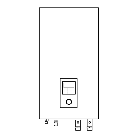
Installation Manual
AIR-TO-WATER HEATPUMP INDOOR UNIT
SXC09*3E5, SXC12*6E5
Required tools for Installation Works
1 Phillips screw driver
2 Level gauge
3 Electric drill
4 Spanner
SAFETY PRECAUTIONS
•
Read the following "SAFETY PRECAUTIONS" carefully before installation.
•
Electrical work must be installed by a licensed electrician. Be sure to use the correct rating and main circuit for the model to be installed.
•
The caution items stated here must be followed because these important contents are related to safety. The meaning of each indication
used is as below. Incorrect installation due to ignoring of the instruction will cause harm or damage, and the seriousness is classifi ed by the
following indications.
•
Please leave this installation manual with the unit after installation.
WARNING
This indication shows the possibility of causing death or serious injury.
CAUTION
This indication shows the possibility of causing injury or damage to properties only.
The items to be followed are classifi ed by the symbols:
Symbol with white background denotes item that is PROHIBITED from doing.
Symbol with dark background denotes item that must be carried out.
•
Carry out test run to confi rm that no abnormality occurs after the installation. Then, explain to user the operation, care and maintenance as
stated in instructions. Please remind the customer to keep the operating instructions for future reference.
Do not use unspecifi ed cord, modifi ed cord, joint cord or extension cord for power supply cord. Do not share the single outlet with other electrical
appliances. Poor contact, poor insulation or over current will cause electrical shock or fi re.
Do not tie up the power supply cord into a bundle by band. Abnormal temperature rise on power supply cord may happen.
Keep plastic bag (packaging material) away from small children, it may cause suffocation.
Do not use pipe wrench to install refrigerant piping. It might deform the piping and cause the unit to malfunction.
Do not purchase unauthorized electrical parts for installation, service, maintenance and etc.. They might cause electrical shock or fi re.
Do not modify the wiring of Indoor Unit for installation of other components (i.e. heater, etc). Overloaded wiring or wire connection points may
cause electrical shock or fi re.
Do not add or replace refrigerant other than specifi ed type. It may cause product damage, burst and injury etc.
Do not use joint cable for Indoor / Outdoor Unit connection cable. Use specifi ed Indoor / Outdoor Unit connection cable, refer to instruction 6
CONNECT THE CABLE TO THE INDOOR UNIT and connect tightly for Indoor / Outdoor Unit connection. Clamp the cable so that no external
force will be acted on the terminal. If connection or fi xing is not perfect, it will cause heat up or fi re at the connection.
For electrical work, follow local wiring standard, regulation and this installation instruction. An independent circuit and single outlet must be used.
If electrical circuit capacity is not enough or defect found in electrical work, it will cause electrical shock or fi re.
For water circuit installation work, follow to relevant European and national regulations (including EN61770) and local plumbing and building
regulation codes.
Engage dealer or specialist for installation. If installation done by the user is defective, it will cause water leakage, electrical shock or fi re.
•
This is a R410A model, when connecting the piping, do not use any existing (R22) pipes and fl are nuts. Using such same may cause abnormally
high pressure in the refrigeration cycle (piping), and possibly result in explosion and injury. Use only R410A refrigerant.
•
Thickness for copper pipes used with R410A must be 0.8mm or more. Never use copper pipes thinner than 0.8mm.
•
It is desirable that the amount of residual oil is less than 40mg/10m.
When install or relocate Indoor Unit, do not let any substance other than the specifi ed refrigerant, e.g. air etc. mix into refrigerant cycle (piping).
Mixing of air etc. will cause abnormal high pressure in refrigeration cycle and result in explosion, injury etc.
1
ACXF60-05520
4
5 Pipe cutter
6 Reamer
7 Knife
8 Gas leak detector
WARNING
9 Measuring tape
10 Megameter
11 Multimeter
12 Torque wrench
ENGLISH ................ 1
ESPAÑOL ............. 32
ITALIANO .............. 63
18 N•m (1.8 kgf•m)
65 N•m (5.5 kgf•m)
1
Advertisement
Table of Contents


Need help?
Do you have a question about the SXC09 3E5 Series and is the answer not in the manual?
Questions and answers