
Related Manuals for Matt:e IP-EVCP-T


Summary of Contents for Matt:e IP-EVCP-T
- Page 1 Single-Phase IP65 Electric Vehicle Charger Protection Units IP-EVCP-T(C) IP-EVCP-R(C) IP-EVCP-M(C) Installation Manual July 2023...
-
Page 2: Table Of Contents
Single-phase EV charger protection unit Contents Product Description Warning Notice Safety Advice Introduction Dimensions & Mounting the unit Touch Plate Assembly Electrical Connections Operating Instructions Status Indicator Specifications Warranty Declaration of Conformity PRODUCT ADVISORY NOTICE This product must be installed by a competent person in accordance with the IET Wiring Regulations, BS7671 (18 Edition or later) and current Building Regulations. -
Page 3: Product Description
PME supplies are feeding Electric Vehicle Chargers. They should NOT be used on premises with 3 phase supplies. This manual covers the IP-EVCP-T(Cxx), IP-EVCP-R(Cxx), IP-EVCP-M(Cxx) models manufactured after July 2023. The units are not intended for any purpose other than that defined within this document. -
Page 4: Introduction
Single-phase EV charger protection unit Introduction matt:e range of Single Phase Electric Vehicle Charger Protection units are designed to protect Electric Vehicle Charging equipment when installed onto single-phase PME infrastructures . All units incorporate an electronic detection circuit and 3 pole contactor. The T version has a double pole isolator and a single terminal on the incoming side of the unit. -
Page 5: Dimensions & Mounting The Unit
Single-phase EV charger protection unit Dimensions P a g e... -
Page 6: Touch Plate Assembly
Single-phase EV charger protection unit Touch Plate Assembly A = Touch Plate B = Touch Plate Support C = Touch Plate Support With Cut Out D = 4 No. M5x12 Screws E = 8 No. 10x10mm Screws F = 4 No. M5 Cage Nut P a g e... -
Page 7: Electrical Connections
Single-phase EV charger protection unit Electrical Connections IP-EVCP-M (Cxx) Connect the supply cable from the distribution board directly to the MCB ‘mains in’ terminals. Connect the outgoing cable to the contactor N, E, & L terminals. If required, connect the CT to the 3 pin connector on the PCB. - Page 8 Single-phase EV charger protection unit IP-EVCP-R (Cxx) Connect the supply cable from the distribution board directly to the RCBO ‘mains in’ terminals. Connect the outgoing cable to the contactor N, E, & L terminals. If required, connect the CT to the 3 pin connector on the PCB.
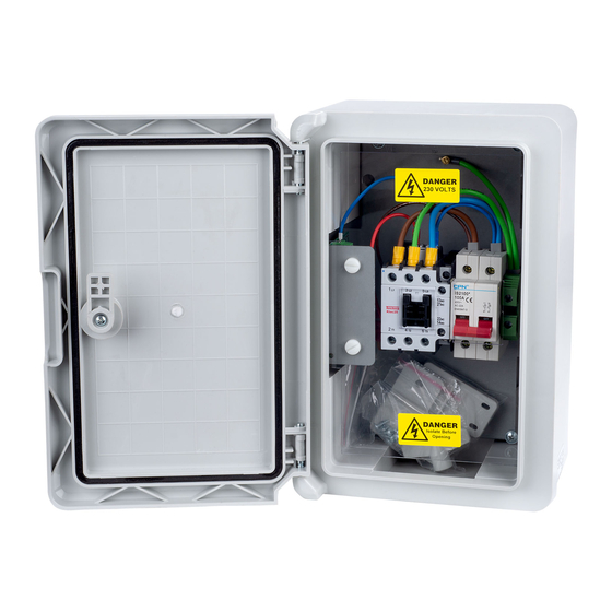
- Page 9 Single-phase EV charger protection unit IP-EVCP-T (Cxx) Connect the supply cable from the distribution board (or meter tails) directly to the isolator ‘Incoming Supply’ terminals. Connect the outgoing cable to the contactor L, E & N terminals. If required, connect the CT to the 3 pin connector on the PCB.
- Page 10 Single-phase EV charger protection unit 10 | P a g e...
-
Page 11: Operating Instructions
Single-phase EV charger protection unit Operating Instructions With the supply switched on the electronic control circuit in unit will continuously monitor the incoming supply voltage. If the incoming supply is within limits, approximately 5 seconds after switching on the contactor will energise and connect the load to the incoming supply and the CPC. -
Page 12: Status Indicator
Single-phase EV charger protection unit LED Status Indicator A dual colour (Red / Green) LED gives a visual indication of the real time status of the unit. 12 | P a g e... -
Page 13: Specifications
The IP-EVCP units are guaranteed for a period of 3 years from the date of manufacture. This warranty is limited to the replacement of faulty components only. t: 01543 227290 e: info@matt-e.co.uk w: www.matt-e.co.uk matt:e Ltd, Unit 1, Langley Brook Business Park, Middleton, Tamworth, B78 2BP 13 | P a g e... -
Page 14: Declaration Of Conformity
EN61439-1&2 2011 Low-voltage switchgear and control gear assemblies. EN60947-3 Low-voltage switchgear and control gear EN61095 Electromechanical contactors EN61009-1 Residual current operated circuit-breakers with integral overcurrent Signed for and on behalf of: matt:e Ltd Place of issue Date Tamworth, England July 2023...
Need help?
Do you have a question about the IP-EVCP-T and is the answer not in the manual?
Questions and answers