Table of Contents
Advertisement
Quick Links
Advertisement
Table of Contents

Related Manuals for NSR Marine NHR-1500

Summary of Contents for NSR Marine NHR-1500
- Page 1 User Manual MF/HF RADIO(GMDSS) NHR-1500 NHR-1500 OM.E 20230116-18...
- Page 2 Any attempt to modify the software on this device in a way not specified by NSR will result in the warranty being void. iv. Notice Please read this manual carefully to ensure proper use before installation and operation of the NHR-1500. NHR-1500 OM.E 20230116-18...
- Page 3 NBDP menu tree & drawings etc. 2021/11/01 1.4, 7.7, App.6 Update the drawings Add Alarm Unit and PN, update the 2022/06/10 1.4, 7, App.5&6 drawings 2022/09/09 1.4, 7, App.6 Update the drawings etc. 2022/10/19 General modification 2023/1/16 7.1 & 7.2 Installation requirements NHR-1500 OM.E 20230116-18...
-
Page 4: Table Of Contents
3.1 Type of Emission Selection ......................43 3.2 Channel & Frequency Selection ....................43 3.2.1 Channel ..........................44 3.2.2 Frequency .......................... 45 3.3 Transmit ............................45 3.3.1 Transmitting Procedure ..................... 45 3.3.2 Transmitting Power Setting ....................46 3.4 Receive ............................46 NHR-1500 OM.E 20230116-18... - Page 5 APPENDIX 1 TECHNICAL SPECIFICATIONS ................... 155 APPENDIX 2 MENU TREE ........................157 APPENDIX 3 NBDP COMMAND AND ABBREVIATION..............159 APPENDIX 4 FREQUENCY TABLES ....................160 APPENDIX 5 SENTENCE DISCRIPTION ................... 173 APPENDIX 6 INSTALLATION DRAWINGS ..................179 NHR-1500 OM.E 20230116-18...
-
Page 6: Overview
DSC (digital selective calling) facilities as well. Conforming to Class A standard set for MF/HF DSC by ITU and IMO regulation, NHR-1500 can be part of onboard GMDSS package for vessels of A2/A3/A4 sea area. NHR-1500 conforms to the regulations of ITU-R M.476-5, ITU-R M.492-6, ITU-R M.493-15, ITU-R M.541-10, IMO MSC.302 (87) [2010], IEC 61097-9, IEC 61097-3, IEC 60945, IEC 62923-1, IEC 62923-2 etc. - Page 7 NHR-1500 USER MANUAL Unit Description Control Unit (NHR-1000C) Control Unit is mainly used for system setting and SSB/DSC operation. Antenna Coupler (NHR-1000A) The Antenna Coupler tunes the antenna to the transmitter. NBDP Terminal (NBD-100) (option) NBDP Terminal is designed for ARQ/FEC communications.
-
Page 8: System Configuration
NHR-1500 USER MANUAL 1.4 System Configuration NHR-1500 consists of a Control Unit, a Transceiver Unit and an Antenna Coupler and a Handset. The options include NBDP Terminal, Printer, Antenna, PSU, etc. STANDARD Q’ty Name Type Part No. Remarks Transceiver Unit... - Page 9 NHR-1500 USER MANUAL OPTIONAL Q’ty Name Type Part No. Remarks N993430 Power Supply Unit NPS-300 N588011 TX/RX Antenna NHA100 N585010/ NXA100/ DSC Watch RX Antenna NXA100A N585011 N502613 NBDP Terminal NBD-100 Keyboard for NBDP NKB-100 N502616 N502615 Alarm Unit NAU-100...
- Page 10 NHR-1500 USER MANUAL NHR-1500 SYSTEM CONFIGURATION NHR-1500 OM.E 20230116-18...
-
Page 11: Basic Operation
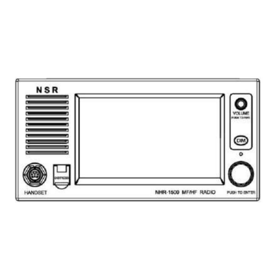
NHR-1500 USER MANUAL 2. BASIC OPERATION 2.1 Control Unit Description ⑦ ⑥ ① ② ③ ⑤ ④ The Control Unit (NHR-1000C) can be operated by key & knob on panel or touch-screen operation. When operating with knob, rotate to select an item on screen and press the knob to confirm the selection. -
Page 12: Ssb Screen
NHR-1500 USER MANUAL 2.3 SSB Screen Indication Meaning RX Signal Level The signal level of receiving. Handset Volume The volume of handset. Speaker Volume The volume of speaker. Connection Icon Connection status of control unit and transceiver unit. Green: OK. -
Page 13: Dsc Watch Scan Screen
NHR-1500 USER MANUAL 2.4 DSC Watch Scan Screen DSC Watch Scan screen includes distress and routine frequencies. Note: The SSB and NBDP communication are not affected during scanning. ① Click [SCAN] to open the DSC WATCH SCAN Screen, and start the scanning. When receiving the signal on appropriate frequency, the scanning stops at that frequency (for example: 2187.5 kHz). -
Page 14: Brightness Adjustment
NHR-1500 USER MANUAL 2.5 Brightness Adjustment There are two ways to adjust the brightness of screen. ① Press the DIM button on panel to adjust the brightness by ten steps, or ② Click [MENU] and adjust the brightness in the [MAIN MENU]: [SYSTEM]-[DISPLAY]-[LCD DIMMER]. -
Page 15: Main Speaker On/Off
NHR-1500 USER MANUAL Note: When the power is turned off, the last status of brightness is stored. Therefore, when the power is turned on, the screen will display with the last brightness before powered off. 2.6 Main Speaker On/Off There are three ways to turn on/off the main speaker (except in DSC communication, alarming and key buzzing). -
Page 16: Distress Scan
NHR-1500 USER MANUAL 2.7.1 Distress Scan Click [DISTRESS SCAN] to open the [DISTRESS SCAN] window and select the frequencies to be scanned. Note: 2 MHz and 8 MHz cannot be deselected. Maximum other three frequencies can be set OFF. 2.7.2 Routine Scan Click [ROUTINE SCAN] to open the [ROUTINE SCAN] window and click to select the frequency desired to scan. - Page 17 NHR-1500 USER MANUAL [NEXT]: Next pages [INTL]: International channels [LOCAL1/LOCAL2]: Local channels [USER]: User channels Note: Should set one routine frequency at least. Refer to APPENDIX 3 – DSC Frequency Table. For example:After setting, the [WATCH SCAN] screen is as follows.
-
Page 18: Auto Acknowledgement Setting
NHR-1500 USER MANUAL 2.8 Auto Acknowledgement Setting Individual, position, polling and test calls can be acknowledged automatically. This is to set on [ACK SETTING] in the [MAIN MENU]-[DSC] menu. Note: When own ship's communication is in high priority, set to manual acknowledgement. -
Page 19: Language
NHR-1500 USER MANUAL The following [SYSTEM SETTING] screen appears: 2.9.1 Language The default menu language is English. Click [LANGUAGE], or rotate the PUSH TO ENTER knob to select [LANGUAGE] then press the knob, to change the menu language. The following knob operations are the same as above. -
Page 20: Audio
NHR-1500 USER MANUAL ② Click [TX MESSAGE] to select MANUAL or AUTO. ③ Set [RX MESSAGE] and [SELFTEST INFO] similarly. ④ You can also set the printer type and port baud rate here. 2.9.3 Audio Click [AUDIO] in [SYSTEM SETTING] to set the key buzzer and alarm buzzer etc. - Page 21 NHR-1500 USER MANUAL 2.9.3.1 KEY BUZZER Click [KEY] to switch the buzzer on or off. 2.9.3.2 ALARM BUZZER Click [ALARM] to switch the alarm buzzer on or off. By setting the [ALARM], alarm that sounds against system faults and message receiving may be enabled or disabled.
-
Page 22: Display Mode Setting
NHR-1500 USER MANUAL 2.9.3.4 ALARM DISTANCE Click [ALARM DISTANCE] to set the alarm distance: OFF: The audio alarm sounds while any distress call is received. 500nm: The audio alarm sounds when a distress call from a ship within 500nm is received. -
Page 23: Date/Time Setting
NHR-1500 USER MANUAL 2.9.5 Date/Time Setting This is to set the date and time for the system. Click [DATE/TIME] in [SYSTEM SETTING] to open the [DATE/TIME SET] screen. There are four items can be set: MODE, DATE-UTC, TIME-UTC and ZONE. - Page 24 NHR-1500 USER MANUAL Date or time cannot be adjusted when they are input from GNSS navigator. If date or time is not input from GNSS navigator, click to enter date and time with the numeric keys in the pop-up window.
-
Page 25: Position Setting
NHR-1500 USER MANUAL 2.9.6 Position Setting This is to set a position used for DSC operations only when GPS input is not available. Do the following to set your position: ① Click [POSITION] in [SYSTEM SETTING]. ② Click [SOURCR] to select [EPFS] or [MANUAL]. - Page 26 NHR-1500 USER MANUAL [MANUAL]: Set the position data manually. For [MANUAL], go to next step. ③ For manual input, click [POS&TIME], use the numeric keys to enter latitude/longitude of your position, and UTC time. To change coordinate, click 1 for North or East; 2 for South or West.
-
Page 27: Timeout Setting
NHR-1500 USER MANUAL You can see the result of setting on SSB screen by clicking [BACK]. Note: When the setting of POSITION input type is [MANUAL], and the message "WARNING: Position data is not updated! " is shown, the Position data was older than 4H. Please update it. -
Page 28: Network Setting
NHR-1500 USER MANUAL [MENU BACK]: Back to the upper menu screen automatically. [SSB]: Close the inactive communications for SSB. [GENERAL DSC]: Close the inactive communications except the distress call. [DISTRESS RX]: Close the inactive communications for the receiving distress call. - Page 29 NHR-1500 USER MANUAL Note:If you want to configure the network, you need to enter the password first in [SERVICE] menu. ① Set IP, Sub Mask and Gateway: Click [NETWORK]-[TCP/IP], the following screen appears: [MODE]: Default Static IP. [IP]: Edit Device IP: 192.168.0.1-192.168.255.255, 172.16.0.1-172.16.31.255.
-
Page 30: Port
NHR-1500 USER MANUAL [STATE]: ON: Enable output sentence via RCOM GROUP. [MULTICAST IP]: RCOM GROUP Default IP. [MULTICAST PORT]: RCOM GROUP Default Port. 2.9.9 Port Click [Port] in [SYSTEM SETTING], the following screen appears: Click [BAM/INS] or [GNSS] to change the port speed. -
Page 31: View An Address
NHR-1500 USER MANUAL Click [ADDRESS] in the [MAIN MENU]-[DSC] menu, you can do the following operations. 2.10.1 View an Address ① Click or move the cursor by rotating the PUSH TO ENTER knob to select the address in list. ② Click [VIEW] to see the details of the address. -
Page 32: Add An Address
NHR-1500 USER MANUAL 2.10.2 Add an Address ① Click [ADD] to add an address. For example, add a group MMSI. ② Click [MMSI], enter the MMSI with the numeric keys in [INPUT]. ③ Click OK to confirm. The [TYPE] is automatically changed to GROUP if you enter the group MMSI. -
Page 33: Delete An Address
NHR-1500 USER MANUAL ⑥ Click [SAVE] and select YES . The address is added in the list. 2.10.3 Delete an Address ① Click or move the cursor by rotating the PUSH TO ENTER knob to select an address in list. -
Page 34: Call To An Address
NHR-1500 USER MANUAL 2.10.4 Call to an Address ① Click or move the cursor by rotating the PUSH TO ENTER knob to select an address in list. ② Click [CALL], you can send a DSC call to the selected address. For example: ... -
Page 35: Program Version
NHR-1500 USER MANUAL 2.11.1 Program Version It is to check the program version at [DIAGOSTICS] menu. Click [PROGRAM VERSION], the following screen appears (for example): The above [HARDWARE] is for the control unit. 2.11.2 LCD Test After clicking [LCD TEST], press the DIM button to test the Display Brightness. Press the PUSH TO ENTER knob to return to the upper menu. -
Page 36: Audio Test
NHR-1500 USER MANUAL KEY test: DIM: Press the DIM button. DISTRESS: Press the DISTRESS button. KNOB test: LEFT/RIGHT/ENT: Turn the PUSH TO ENTER knob to left and right, then press it. LEFT2/RIGHT2/ENT2: Turn the PUSH TO PWR knob to left and right, then press it. -
Page 37: Error Log
NHR-1500 USER MANUAL Click the items to test the corresponding audio. Note: the ALARM buzzer should be set to ON while do the test. 2.11.5 Error Log ① Click [ERROR LOG] on the [DIAGNOSTICS] screen. ② With [ERROR LOG] selected, the screen shown below appears. -
Page 38: User Manager
NHR-1500 USER MANUAL 2.12 User Manager Click [USER] on the [MAIN MENU] screen. The [USER MANAGER] menu appears. 2.12.1 Channel List Click [CHANNEL LIST], the following screen appears: NHR-1500 OM.E 20230116-18... - Page 39 NHR-1500 USER MANUAL ① View/Edit a channel Move the cursor to the wanted channel, click [VIEW], the [CHANNEL EDIT] screen appears: You can click the TYPE, BAND, RX frequency or TX frequency to edit. NHR-1500 OM.E 20230116-18...
- Page 40 NHR-1500 USER MANUAL Click OK to confirm the input. Click SAVE and choose “YES” to save the edition, “NO” to discard the edition. ② Add a channel Click [ADD], open the [CHANNEL EDIT] screen. The operation is same as above.
- Page 41 NHR-1500 USER MANUAL Click [DELETE], delete the channel directly. ④ Call Move the cursor to the wanted channel. Click [CALL], open the SSB screen to start SSB communication. NHR-1500 OM.E 20230116-18...
-
Page 42: Alert List
NHR-1500 USER MANUAL 2.12.2 Alert List Click [USER] on the [MAIN MENU] screen. The [USER MANAGER] menu appears. Select [ALERT LIST] to show the following menu. [VIEW]: Check the details of the alert selected. [MUTE]: Mute the alert. [ACK]: Acknowledge the alert. - Page 43 NHR-1500 USER MANUAL Note: [RESET] is only used for DISTRESS RX alert reset. Alert mark description: MARK PRIORITY STATE EMERGENCY ALARM ACTIVE ACTIVE-UNACKNOWLEDGED ACTIVE-SILENCED ALARM ACTIVE-ACKNOWLEDGED ACTIVE-RESPONSIBILITY TRANSFERRED RECTIFIED-UNACKNOWLEDGED ACTIVE-UNACKNOWLEDGED ACTIVE-SILENCED WARNING ACTIVE-ACKNOWLEDGED ACTIVE-RESPONSIBILITY TRANSFERRED RECTIFIED-UNACKNOWLEDGED CAUTION ACTIVE Alert description:...
-
Page 44: Daily Test
NHR-1500 USER MANUAL Alert Configuration Table: Alert Alert Alert Alert Escalation Permission Permission Transfer identifier instance category priority Properties Acknowledge of Responsibility 3122 WARNING WARNING 3008 WARNING WARNING 3062 WARNING WARNING 3062 WARNING WARNING Note: The principles of responsibility transfer Reduction of the high-priority of alerts, recognizes that a system may have knowledge about the context of some alert(s) of another system. - Page 45 NHR-1500 USER MANUAL Click [TEST] and confirm “YES” to start the test of PA, FIL and DSC. The test result is shown as below: NHR-1500 OM.E 20230116-18...
-
Page 46: Dsc Log
NHR-1500 USER MANUAL 2.12.4 DSC Log DSC log also can be checked at [USER] menu. Click [DSC LOG], and repeat click [LIST] to check the following screens: NHR-1500 OM.E 20230116-18... - Page 47 NHR-1500 USER MANUAL NHR-1500 OM.E 20230116-18...
-
Page 48: Ssb Operation
NHR-1500 USER MANUAL 3. SSB OPERATION You can make a voice call at SSB screen or from [MAIN MENU]-[USER]-[CHANNEL LIST]-[CALL]. 3.1 Type of Emission Selection The type of emission can be selected among SSB (J3E), CW (A1A) etc. , default is [SSB]. -
Page 49: Channel
NHR-1500 USER MANUAL 3.2.1 Channel ① Click [CH]. Channel setting window The channel can be entered by entering the number on the right. See below for details: - Click the number to enter channel then click OK. Or - Select band and band channel with the following knobs: ... -
Page 50: Frequency
NHR-1500 USER MANUAL 3.2.2 Frequency ① Click [TX] or [RX]. Frequency Setting Window 02182.0 02182.00 ② Enter frequency by one of the methods below. Enter frequency with the numeric keys: Use the numeric keys to enter frequency then click OK. For example, to enter 2126 kHz, key in 0, 2, 1, 2, 6, 0. -
Page 51: Transmitting Power Setting
NHR-1500 USER MANUAL ① Click the PTT switch on the handset. Tuning is automatically performed at first transmission after frequency is changed. For manual tuning, click [TUNE] on the SSB screen. If tuning fails, the message "ERR" appears and the output power is automatically set to [LOW]. -
Page 52: Squelch
NHR-1500 USER MANUAL 3.4.2 Squelch Squelch on/off The squelch mutes the noise output in the absence of an incoming signal. Click [SQL] to alternately turn squelch on and off on the SSB screen. When radio noise is too jarring during stand-by condition, it can be muted by activating the squelch, and ON is displayed on the SSB screen. -
Page 53: Dsc Operation
NHR-1500 USER MANUAL 4. DSC OPERATION 4.1 DSC Description DSC (Digital Selective Calling) is an important mean for emergency calls at sea. It’s a part of GMDSS (Global Maritime Distress and Safety System) set by IMO (International Marine Organization). DSC should be primarily used for distress, urgency and safety call and response to such calls, in addition, it can be used for general service between ship to ship and ship to shore station. -
Page 54: Audio Alarms
NHR-1500 USER MANUAL Station ID (MMSI) Ship station ID: MIDxxxxxx Coast station ID: 00MIDxxxx Group ID: 0MIDxxxxx Above, MID (Maritime Identification Digits): Country code, x…x: Digital number. Priority Distress: In grave and imminent danger and request immediate assistance. -
Page 55: Dsc Call Screens
NHR-1500 USER MANUAL Alarm Frequency (interval) Distress Count Down 2000Hz 500ms, Silence 500ms Two Tone (Distress) 2200Hz 250ms, 1300Hz 250ms Distress Ack 2200Hz 500ms, 1300Hz 500ms Urgency 2200Hz 250ms, Silence 250ms Urgency Ack 2200Hz 500ms, Silence 500ms Genernal (Routine, Routine Ack) - Page 56 NHR-1500 USER MANUAL Individual call: The marks "*", "-" appear on the DSC receiving screen in the following conditions: "*" indicates a corrupt character in received data. "-" indicates missing digits after decimal point when receiving position data with no information for expansion (expansion: digits after decimal point).
-
Page 57: Dsc Distress Operation
NHR-1500 USER MANUAL Individual call: The contents of other types of TX calls are similar to the above. 4.2 DSC Distress Operation Distress operation overview: When own ship in distress: ① Press the DISTRESS button to send a distress call. - Page 58 NHR-1500 USER MANUAL PUSH TO ENTER knob Cover* DISTRESS button *: The DISTRESS button is covered to prevent false alarm. The audio alarm sounds while pressing the button, and the button flashes. The countdown message appears on the screen while pressing the DISTRESS button (3S → 2S → 1S ). For example:...
- Page 59 NHR-1500 USER MANUAL (2) After the distress call has been sent, the screen changes as below. Wait to receive the distress acknowledge call from a coast station. The elapsed time since transmission is displayed. At this time, the icons for other DSC received messages except the distress acknowledge call are not displayed.
- Page 60 NHR-1500 USER MANUAL During sending During waiting acknowledgement ① [OPTION]- [Pause]: ① [OPTION]- [Pause]: ② [OPTION]- [Start]: ② [OPTION]- [Start]: NHR-1500 OM.E 20230116-18...
- Page 61 NHR-1500 USER MANUAL ③ [OPTION]- [Cancel]: ③ [OPTION]- [Cancel]: Please see the details in Section 4.2.4 - Cancel a Distress Call. (4) During waiting acknowledgement, you can also change the follow-up communication frequency. For example: Click [OPTION]-[Change]-[2182.0 kHz]to change the SSB TX/RX frequency to 2182.0 kHz.
- Page 62 NHR-1500 USER MANUAL (5) You can also click [Resend] to resend the distress call on 2/4/6/8/12/16 MHz. NHR-1500 OM.E 20230116-18...
- Page 63 NHR-1500 USER MANUAL Also, you can re-send the distress alert manually by pressing the DISTRESS button for 3 seconds. (6) When the distress acknowledge call is received, the audio alarm sounds, the LED of DISTRESS button flashes and the icon for DISTRESS ACK received ( ) appears.
- Page 64 NHR-1500 USER MANUAL ② Click [NATURE] to select nature of distress, among the following 11 selections. ③ Click [POSITION], select [EPFS], [MANUAL] or [NO INFO] in pop-up window. [EPFS]: The position information from EPFS is automatically shown. [MANUAL]: Input your position manually.
- Page 65 NHR-1500 USER MANUAL ④ Use the numeric keys to enter latitude/longitude of your position, and UTC time. To change coordinate, click 1 for North or East; 2 for South or West. After enter each data, click OK. ⑤ If you want to select the desired DSC frequency, click [DSC FREQ] or rotate the PUSH TO ENTER knob to select [DSC FREQ] then push the knob, select the single DSC frequency or the multi frequencies.
- Page 66 NHR-1500 USER MANUAL select among 2 MHz, 4 MHz, 6 MHz, 8 MHz, 12 MHz and 16 MHz. 2 MHz and 8 MHz are automatically selected and cannot be excluded. Click the frequency to select or deselect and click SET SELECT to confirm. Each clicking displays (selected) or removes (deselected) the frequency in [DSC FREQ] area.
-
Page 67: Receive A Distress Call
NHR-1500 USER MANUAL ⑦ When the distress acknowledge call is received, use the telephone or telex to communicate with the coast station. For NBDP, follow the procedure in “NBDP operation manual”. For SSB, please refer to Section 4.2.1.1 (6). If you selected multi frequencies at step ⑤, you can communicate via telephone, on the communication frequency which the distress acknowledge is first received. - Page 68 NHR-1500 USER MANUAL If you do not receive the distress acknowledgement from a coast station in about 3 minutes after receiving a distress call, please follow the flow charts in this section to determine your action. Note: An asterisk (*) appearing in a distress alert message indicates an error at the asterisk’s location.
- Page 69 NHR-1500 USER MANUAL Note: You must wait at least 3 minutes before you can acknowledge the distress call so that the coast station has time to send a distress acknowledgement. (4) Send the DSC distress acknowledgement to ship in distress (on MF band): You can transmit the distress acknowledgement to the ship in distress only when you do not receive it from a coast station and you are able to aid the ship in distress.
- Page 70 NHR-1500 USER MANUAL (2) Wait 3 minutes after receiving a distress call. (3) Relay the distress call in the following cases: You have not received a distress acknowledgement from a coast station within 3 minutes after receiving a distress call.
- Page 71 NHR-1500 USER MANUAL Flow chart of action for ship receiving distress call on HF band: (7) Send the distress relay to coast station (on HF band): ① Click [OPTION], select [Relay] to open the composing screen for the distress relay individual.
- Page 72 NHR-1500 USER MANUAL ② Click [TO], enter the MMSI of the coast station, where to send the distress relay, with the numeric keys then click OK to confirm. ③ Click [CALL], the screen changes to the [TX MESSAGE-RELAY] for transmitting. After transmitting, the [WAIT ACK] screen appears.
-
Page 73: Relay A Distress Call
NHR-1500 USER MANUAL When the distress relay individual acknowledgement from the coast station is received, the audio alarm sounds and a pop-up message appears. Click CLICK to silence the alarm and erase the pop-up message. Communicate with the coast station by telephone, over the frequency specified. If you do not receive the distress acknowledgement from a coast station, click [OPTION], select [RESEND] to transmit the distress relay again, or select [Quit] to finish the distress relay. - Page 74 NHR-1500 USER MANUAL ③ With [TO] selected, click to enter the MMSI where to send the distress relay by numeric keys in [INPUT]. Click OK to confirm. You can also rotate the PUSH TO ENTER knob to a digit to input or modify.
- Page 75 NHR-1500 USER MANUAL ④ With [DISTRESS ID] selected, click to choose [INPUT] or [NO INFO]. ⑤ For [INPUT], go to step ⑥. For [NO INFO], go to step ⑦. ⑥ Enter the ID (MMSI) of the ship in distress with the numeric keys then click OK.
- Page 76 NHR-1500 USER MANUAL ⑧ With [POSITION] selected, click to select [EPFS], [MANUAL] or [NO INFO]. For [MANUAL], go to step ⑨. For others, go to step ⑩. ⑨ Use the numeric keys to enter latitude and longitude of the ship in distress. Switch coordinates: Click 1 to switch to North (East for longitude);...
- Page 77 NHR-1500 USER MANUAL ○ Click [CALL], the distress relay is transmitted to the coast station. After transmitting, the [WAIT ACK] screen appears. The elapsed time since transmitting is displayed. When the distress relay individual acknowledgement from the coast station is received, the audio alarm sounds and a pop-up message appears.
- Page 78 NHR-1500 USER MANUAL [Hold]: You can hold the distress relay ( changes to ) and activate it again by clicking [OPTION]. Note: If you click [2182] to the SSB screen, the operation is held automatically, and click [TASK] to return to DSC screen.
- Page 79 NHR-1500 USER MANUAL ② With [TO] selected, enter the area that where to send the distress relay area with the numeric keys in [INPUT]. Click OK to confirm. The area call is for sending a call to all ships within the area you designated.
-
Page 80: Cancel A Distress Call
NHR-1500 USER MANUAL ③ With [DISTRESS ID] selected, enter the ID (MMSI) of the ship in distress. Refer to Section 4.2.3.1 ④~⑥. ④ With [NATURE] selected, click to select nature of distress. Refer to Section 4.2.3.1 ⑦. ⑤ With [POSITION] selected, enter latitude and longitude of the ship in distress. Refer to Section 4.2.3.1 ⑧~⑨. - Page 81 NHR-1500 USER MANUAL ① Click [OPTION], then select [Cancel]. ② Click YES to cancel, the sending screen appears, then wait till the following SELECT FREQUENCY screen appears: NHR-1500 OM.E 20230116-18...
- Page 82 NHR-1500 USER MANUAL ③ Select a frequency (For example: 2 MHz). The following screen appears, the color of “SELECT” changes from red to black. The communication frequency changes correspondingly. ④ Pick up the handset, make a voice announcement with all ships via radiotelephone referring to the message on screen.
-
Page 83: Dsc General Calls
NHR-1500 USER MANUAL ⑥ Click [FINISH] to finish the operation. 4.3 DSC General Calls General procedure for non-distress DSC calls: The procedure for sending and receiving non-distress DSC messages is similar among different message types. The following is an example of the procedure for an individual call. - Page 84 NHR-1500 USER MANUAL (1) Click [DSC MSG], or click [MENU] and choose [DSC] – [MESSAGE], then click [GENERAL MESSAGE] in [MESSAGE]. (2) Click [MSG TYPE] or rotate the PUSH TO ENTER knob to select [MSG TYPE] then push the knob, select [INDIVIDUAL] among INDIVIDUAL, GROUP, AREA, POSITION and TEST.
- Page 85 NHR-1500 USER MANUAL (4) Click [PRIORITY] or rotate the PUSH TO ENTER knob to select [PRIORITY] then push the knob, select [ROUTINE], [SAFETY] or [URGENCY]. (5) The [COMM FREQ] is automatically set to the same pair frequency as the DSC frequency. If you change the communication frequency, set [DSC FREQ] before setting [COMM FREQ].
- Page 86 NHR-1500 USER MANUAL Routine priority ① Click to select the DSC band, for example 6M. The menu shown below appears depending on the band selected. ② Click to select DSC frequency. The screen shows the DSC frequency at [DSC FREQ]. And the [COMM FREQ] is automatically set to the same pair frequency as the DSC frequency.
- Page 87 NHR-1500 USER MANUAL Urgency or safety priority Click to select the frequency, for example 8414.5 kHz. The [COMM FREQ] is automatically set to the same pair frequency as the DSC frequency. If you change the communication frequency, go to step (7). If not, go to step (8).
- Page 88 NHR-1500 USER MANUAL Note: When you send an individual call to a coast station, [COMM FREQ] is automatically set to “POSITION” or “NO INFO”. “NO INFO” lets the receiving station set the communication frequency. For example: (8) Click [CALL] to send the individual call.
- Page 89 NHR-1500 USER MANUAL The timer starts counting up the time since the call is sent. After the call is sent, the equipment waits for acknowledgement of the call, showing the [WAIT ACK] screen as below. You can also do the option: [Hold]/[Quit]/[Resend].
- Page 90 NHR-1500 USER MANUAL There are three types of ACK messages: [INDIVIDUAL ACK], [INDIVIDUAL ACK] (NEW FREQ) and [UNABLE ACK]. (10) Do one of the following depending on the message type shown at step (9). Individual acknowledge call received: ① Click CLICK to silence the audio alarm and erase the pop-up message.
- Page 91 NHR-1500 USER MANUAL ② After you have completed communications, click [OPTION], select [Quit] to SSB screen. Unable to acknowledge call received: ① Click CLICK to silence the audio alarm and erase the pop-up message. The reason for [UNABLE ACK] is displayed on the screen.
- Page 92 NHR-1500 USER MANUAL Reason for unable to acknowledge NO REASON CONESTION* BUSY QUEUE STA. BARRED NO OPERATOR TEMP. NO ONE EUT DISABLED CH UBABLE MODE UBABLE NON-ARMED MED TRANSPORT *: Coast station use ② Click [OPTION], select [Quit] to SSB screen.
- Page 93 NHR-1500 USER MANUAL (1) Send able acknowledge call ① Click [Accept], send the able acknowledge call. ② Communicate by radiotelephone or NBDP. ③ After you have completed communications, click [OPTION] to select [Quit]. (2) Send unable acknowledge call ① Click [Unable].
- Page 94 NHR-1500 USER MANUAL ② With [REASON] selected, click [CALL] to send unable acknowledge call. (3) Send able acknowledge call and change frequency ① Click [Propose], the following screen appears. ② Click [COMM FREQ] or rotate the PUSH TO ENTER knob to select [COMM FREQ] then push the knob.
-
Page 95: Group Call
NHR-1500 USER MANUAL ⑤ Communicate by radiotelephone or NBDP. ⑥ After you have completed communications, click [OPTION] to select [Quit]. 4.3.2 Group Call Group call is used to call a specific group by specifying its group MMSI. 4.3.2.1 Send a group call (1) Click [DSC MSG], or click [MENU] and choose [DSC] –... - Page 96 NHR-1500 USER MANUAL (3) With [TO] selected, enter the group MMSI that where to send the group call in [INPUT], then click OK to confirm. (4) [PRIORITY] is automatically selected to [ROUTINE]. (5) Set [DSC FREQ] and [COMM FREQ] if you need. The procedure is same as Section 4.3.1.1 (6) - Routine priority.
- Page 97 NHR-1500 USER MANUAL (6) After finish setting of DSC/communication frequency, click [CALL] to send the group call. The screen changes as below. Communicate by radiotelephone or NBDP. (7) After you have completed communications, click [OPTION], select [Quit] and click YES to SSB screen.
-
Page 98: Area Call
NHR-1500 USER MANUAL 4.3.2.2 Receive a group call Group MMSI must be registered in order to receive a group call. Refer to Section 2.10. When a group call is received, the audio alarm sounds. The icon ( ) appears in the tab area, and the pop-up message "RECEIVED A DSC MESSAGE. - Page 99 NHR-1500 USER MANUAL 4.3.3.1 Send an area call (1) Click [DSC MSG], or click [MENU] and choose [DSC] – [MESSAGE], then click [GENERAL MESSAGE] in [MESSAGE]. (2) Click [MSG TYPE] or rotate the PUSH TO ENTER knob to select [MSG TYPE] then push the knob, select [AREA].
- Page 100 NHR-1500 USER MANUAL (4) Click [PRIORITY] to select [URGENCY] or [SAFETY]. (5) Set [DSC FREQ] and [COMM FREQ] if you need. The procedure is the same as Section 4.3.1.1 (6) - Urgency or safety priority. (6) Click [CALL] to send the call. The screen changes as below.
- Page 101 NHR-1500 USER MANUAL (8) You can also do the option: [Hold] or [Resend]. 4.3.3.2 Receive an area call When you receive a geographical area message, the audio alarm sounds. The icon ( ) appears in the tab area, and the pop-up message "RECEIVED A DSC MESSAGE. AREA" appears.
-
Page 102: Position Call
NHR-1500 USER MANUAL (1) Click CLICK to silence the audio alarm and erase the pop-up message. The frequency is automatically tuned to the received frequency. (2) Watch on the working frequency. Communicate by radiotelephone or NBDP. (3) After you have completed communications, click [OPTION] to select [Quit]. - Page 103 NHR-1500 USER MANUAL 4.3.4.1 Request other ship's position (1) Click [DSC MSG], or click [MENU] and choose [DSC] – [MESSAGE], then click [GENERAL MESSAGE] in [MESSAGE]. (2) Click [MSG TYPE] or rotate the PUSH TO ENTER knob to select [MSG TYPE] then push the knob, select [POSITION].
- Page 104 NHR-1500 USER MANUAL (4) [PRIORITY] is automatically selected to [SAFETY]. (5) Click [DSC FREQ] to set the DSC frequency. (6) Click [CALL] to send position call. The screen changes as below. (7) After the call has been sent, the [WAIT ACK] screen appears as below. The elapsed time since sending the call is displayed.
- Page 105 NHR-1500 USER MANUAL (8) When you receive an acknowledge message, the audio alarm sounds and a popup message appears. (9) Click CLICK to silence the audio alarm and erase the pop-up message. If you receive and unable acknowledge message (no position information), the screen is as follows:...
- Page 106 NHR-1500 USER MANUAL (10) Click [OPTION], select [Quit] to back to SSB screen. 4.3.4.2 Receive a position request call You can enable automatic acknowledge of position request with [POSITION] on the [ACK SETTING] menu. Automatic reply When another ship requests your position and the setting of [POSITION] on the [ACK SETTING] menu is [AUTO], the equipment automatically transmits a reply.
- Page 107 NHR-1500 USER MANUAL Manual reply When a position request message is received and the setting of [POSITION] on the [ACK SETTING] menu is [MANUAL], send the reply manually. When you receive a position request call, the audio alarm sounds. The icon ( ) appears in the tab area, and the pop-up message "RECEIVED A DSC MESSAGE.
- Page 108 NHR-1500 USER MANUAL (1) To silence the audio alarm, click CLICK. (2) Click [OPTION], do the operation as follows. Send the ACK with position information: Click [Accept], send position information of own ship. To send the ACK with no position information:...
-
Page 109: Test Call
NHR-1500 USER MANUAL Click [Unable]. The screen changes as below. (3) After the ACK is finished, click [OPTION] to select [Quit]. 4.3.5 Test Call 4.3.5.1 Send a test call (1) Click [DSC MSG], or click [MENU] and choose [DSC] – [MESSAGE], then click [GENERAL MESSAGE] in [MESSAGE]. - Page 110 NHR-1500 USER MANUAL (2) Click [MSG TYPE] or rotate the PUSH TO ENTER knob to select [MSG TYPE] then push the knob, select [TEST]. (3) Click [TO], enter the MMSI where to send the test call in [INPUT], then click OK to confirm.
- Page 111 NHR-1500 USER MANUAL call is displayed. (6) When you receive an acknowledge message, the audio alarm sounds and a popup message appears. (7) Click CLICK to silence the audio alarm and erase the pop-up message. (8) Click [OPTION], select [Quit] to back to SSB screen.
- Page 112 NHR-1500 USER MANUAL 4.3.5.2 Receive a test call Automatic acknowledge When a test call is received with [AUTO] setting on [TEST] of the [ACK SETTING] menu, an acknowledgement is sent automatically. Manual reply When a test call is received and the setting of [TEST] on the [ACK SETTING] menu is [MANUAL], send the acknowledgement manually.
- Page 113 NHR-1500 USER MANUAL (2) Click [OPTION], choose one of the operations: [Hold], [Quit] or [Accept]. If you click [Accept], the test acknowledgement will be sent. After the acknowledgement is finished, click [OPTION] to select [Quit]. NHR-1500 OM.E 20230116-18...
-
Page 114: Polling Call
NHR-1500 USER MANUAL 4.3.6 Polling Call Polling means that another ship wants to confirm if it is within communication range of own ship. 4.3.6.1 Automatic reply When a polling request message is received with [AUTO] setting on [POLLING] of the [ACK SETTING] menu, an acknowledgement is sent automatically. - Page 115 NHR-1500 USER MANUAL (2) Click [OPTION], choose one of the operations: [Hold], [Quit] or [Accept]. If you click [Accept], the polling acknowledgement will be sent. After the acknowledgement is finished, click [OPTION] to select [Quit]. NHR-1500 OM.E 20230116-18...
-
Page 116: Nbdp Operation
NHR-1500 USER MANUAL 5. NBDP OPERATION 5.1 NBDP Overview 5.1.1 Terminal Description ③ ⑤ ① ② ④ ⑬ Dialogue Area ⑭ Message Area ⑨ ⑥ ⑧ ⑩ ⑦ ⑪ ⑫ Content Description Mode Communication mode: ARQ/Broadcast FEC/Selective FEC etc. State Communication status. -
Page 117: Menu Operation
NHR-1500 USER MANUAL 5.1.2 Menu Operation NBDP Terminal (NBD-100) main menu includes the following items: 5.1.2.1 Own Data When NBD-100 is powered on for the first time, typically during installation, the vessel’s own data shall be programmed, including MMSI (9-digit identifier assigned to own ship), Other ID (Selective call No), Answerback Code. - Page 118 NHR-1500 USER MANUAL Click to enter the password. Then you can set Own data if the password is correct. NHR-1500 OM.E 20230116-18...
- Page 119 NHR-1500 USER MANUAL MMSI Setting Click the line of [MMSI], the soft keypad and cursor appear (same as below), then enter the MMSI. You can also use the keyboard connected to NBD-100. You can click , discard the operation and return to the upper menu.
- Page 120 NHR-1500 USER MANUAL Answerback Code Setting Click the line of [Answerback Code] to enter the Answerback Code. Slave Delay Adjusting Click the line of [Slave Delay], adjust the time (range: 0~40 ms) until the ARQ test is successful with the coast station.
- Page 121 NHR-1500 USER MANUAL Outbox Message Click [Outbox Msg] to check and print the transmitted messages which have been saved. Click to open the selected message, the following screen appears: NHR-1500 OM.E 20230116-18...
- Page 122 NHR-1500 USER MANUAL Click Print to print the message. Click Back to return to the upper menu. New Message Click [New Msg] to check those new messages which can be sent. If you want to add a new message, click and the following window appears: NHR-1500 OM.E 20230116-18...
- Page 123 NHR-1500 USER MANUAL You can click New Msg to input the new message, or click USB Drive to select the file in U disk. For example: (1) Click New Msg, the following window appears: ① Enter the new message name by the pop-up soft keypad at [Message Name].
- Page 124 NHR-1500 USER MANUAL (2) Click USB Drive, the following window appears: NHR-1500 OM.E 20230116-18...
- Page 125 NHR-1500 USER MANUAL ① Click [UDISK0], then click to select the file in it, for example: TEST2.TXT. ② Then the TEST2.TXT.file has been added in [New Msg] as follows: NHR-1500 OM.E 20230116-18...
- Page 126 NHR-1500 USER MANUAL (3) You can also edit the saved new message by clicking [New Msg] and choose the message which want to be edited. Inbox Message Click [Inbox Msg] to check and print the received FEC messages which have been saved.
- Page 127 NHR-1500 USER MANUAL Delete message or file You can also select a message or a log file by clicking and holding for a while until the following screen appears: Choose “YES” to delete and “NO” to discard the operation.
- Page 128 NHR-1500 USER MANUAL Click Stations key on the main screen. You can use, add, edit or delete a station in the list. Select a station from the list Click one station, for example “gz12140”. NHR-1500 OM.E 20230116-18...
- Page 129 NHR-1500 USER MANUAL Click to select the station to communicate with. Add a station to the list Click to add a new station. After entering, close the soft keypad and click to save the setting. Note: If you don’t click , the setting will not be saved.
- Page 130 NHR-1500 USER MANUAL Edit a station Click one station, for example: “gz12140”. Click to edit the station: After editing, don’t forget to save the information by clicking You can also click to select the station to communicate with. If you want to delete the station (for example: “gz838”), click...
- Page 131 NHR-1500 USER MANUAL Choose “YES” to delete or “NO” to discard the operation. 5.1.2.4 Frequency list You can check ITU NBDP frequencies in the frequency list. The first six frequencies are used for GMDSS distress communication. Click Frequency key on the main screen to check the frequency list.
- Page 132 NHR-1500 USER MANUAL You can also select one pair of frequencies from the list for current ARQ/FEC communication. 5.1.2.5 System Setting Click Settings key on the main screen to enter System Settings: NHR-1500 OM.E 20230116-18...
- Page 133 NHR-1500 USER MANUAL Language The default menu language is English. Click to select other languages. Dimmer Click the green dot in the [Dimmer] and drag left or right to adjust the brightness of screen. Date/Time Setting This is to set the UTC date and time for the system.
- Page 134 NHR-1500 USER MANUAL Time Mode Setting Click in the [Time Mode] to change the time mode between UTC and LMT (local time). Print Interval Setting The print interval is used to set a sending interval parameter of each line to meet the receiving efficiency of different printers.
- Page 135 NHR-1500 USER MANUAL Note: After the system setting is completed, click to save the setting. The system will be rebooted. NHR-1500 OM.E 20230116-18...
- Page 136 NHR-1500 USER MANUAL 5.1.2.6 Sign Out Click Sign Out key on the main screen to quit the system. The following screen appears: NHR-1500 OM.E 20230116-18...
- Page 137 NHR-1500 USER MANUAL Click “NBDP” to enter again. NHR-1500 OM.E 20230116-18...
-
Page 138: Nbdp Communication
NHR-1500 USER MANUAL 5.2 NBDP Communication There are three modes, ARQ, Broadcast FEC and Selective FEC, in NBDP. You can initiate a call by selecting one mode. ARQ (Automatic Repetition Request): a mode where two stations can communicate simultaneously. The direction is changed with an “over”... - Page 139 NHR-1500 USER MANUAL ① While you click ARQ key on the main screen, the following screen with tips may appears: ② In ARQ mode, the default status is to wait for receiving (connection). To call (connect) actively, you need to click CALL below, and wait for connecting (State changes to “Calling”).
- Page 140 NHR-1500 USER MANUAL NHR-1500 OM.E 20230116-18...
- Page 141 NHR-1500 USER MANUAL Note: If connection fails,State changes to “IDLE”, and the following notice appears, please wait at least 120s before recall. ③ There are two methods to prepare the message to be sent. Load a message from [NEW Msg], [Inbox Msg] or [Outbox Msg] which was compiled in Section 5.1.2.2.
- Page 142 NHR-1500 USER MANUAL For example: click [NEW Msg]. Select a message to load it into Message Area: The message can also be edited after loaded in. directly. Type in a message Enter the message by the pop-up soft keypad in Message Area.
-
Page 143: Fec Communication
NHR-1500 USER MANUAL ⑤ After the communication is completed, click SAVE to save the communication log. The log will be stored in [Log File]. 5.2.3 FEC Communication There are two FEC modes, Broadcast FEC and Selective FEC. The operation is almost same. For example: Broadcast FEC. - Page 144 NHR-1500 USER MANUAL ① Click Broadcast FEC key on the main screen, the following screen with tips may appears: ② Then wait to receive the broadcast FFC. After finishing the receiving, you can click SAVE to save the message in [Inbox Msg].
- Page 145 NHR-1500 USER MANUAL ③ In FEC mode, you can send the message at the Waiting to RX status. Prepare the message to be sent. Refer to the section 5.2.2 ③. Click SEND to send the message. The screen changes as follows: After the communication is completed, click SAVE to save the sent message.
- Page 146 NHR-1500 USER MANUAL NHR-1500 OM.E 20230116-18...
-
Page 147: Cw Operation
NHR-1500 USER MANUAL 6. CW OPERATION (1) At the SSB screen, click [MODE] to select the type of emission as [CW]. (2) Rotate the VOLUME knob to adjust the volume of main speaker (Clockwise: volume up, Anti-clockwise: volume down until muted). -
Page 148: Installation
Incorrectly installed antennas will degrade the performance of the radio equipment and will reduce the range of radiocommunications. There are two antennas for NHR-1500, one TX/RX antenna and one DSC WK antenna. 7.1.1 TX/RX Antenna Location and choice of TX/RX antenna: a. -
Page 149: Dsc Watch Rx Antenna
Put a sign “DANGER HIGH VOLTAGE” aside the antenna or on an enclosure around to prevent from being touching. Notice: Alternative antenna (customer supplied) instead of NSR antenna can be used on NHR-1500. Such antenna should meet the requirements set as above and be approved by NSR in advance. 7.1.2 DSC Watch RX Antenna... -
Page 150: Antenna Coupler
NXA100/NXA100A whip antenna with pre-amplifier are supplied by NSR for DSC watch keeping. Notice: Alternative antenna (customer supplied) instead of NSR antenna can be used on NHR-1500. Such antenna should meet the requirements set as above and be approved by NSR in advance. -
Page 151: Installation
NHR-1500 USER MANUAL 7.2.1 Installation The Antenna Coupler is designed watertight. The Antenna Coupler should, as a general rule, be located in an outdoor position below and close to the antenna. The Antenna Coupler should normally be located as close to the antenna as possible, and so that the down lead wire/cable from the antenna should be as vertical as possible. -
Page 152: Transceiver
NHR-1500 USER MANUAL c. Grounding levels External ground plate Best ground points Copper screen Copper foil Stainless steel stanchion Through mast Acceptable ground point Through hull Metal water tank Engine block Undesirable ground points Ship’s DC battery ground Gas or electrical pipe... -
Page 153: Control Unit
NHR-1500 USER MANUAL 7.4 Control Unit The control unit could be mounted on the table, on the wall, the bulkhead using the bracket supplied. For flush-type mount, refer to cutting drawing in this manual. Select proper place to install the unit to avoid sea water and don’t be exposed to direct sunlight. -
Page 154: Alarm Unit
The alarm unit could be mounted as table type or flush-type, please refer to the drawings in this manual. 7.8 Power Supply The NHR-1500 installation should be powered from the ship's main source of electrical energy. In addition, it should be possible to operate the installation from an alternative source of electrical energy including a reserve source of energy. -
Page 155: Connection
NHR-1500 USER MANUAL 7.9 Connection 7.9.1 Cables to Antenna Coupler Between antenna coupler and transceiver unit, there are two cables, one RF cable and one power cable. Together with the coupler, there are two short cables with connectors, one for RF and one for Power Supply. There is another extended short cable supplied for easy connection. - Page 156 NHR-1500 USER MANUAL ② With [MMSI] selected, the screen shown below appears. Enter the MMSI. Click OK to confirm the input. ③ Click [SET] and choose YES to confirm the setting. And MMSI will be locked afterwards. The “LOCK” appears after clicking [MMSI SETTING] again.
- Page 157 NHR-1500 USER MANUAL NOTE: Without a programmed MMSI, the DISTRESS button will not work! The [DSC MSG] cannot be opened either if the MMSI has not been programmed during installation. To change or reprogram a new MMSI, please contact NSR or local agent.
-
Page 158: Maintenance
NHR-1500 USER MANUAL 8. MAINTENANCE 8.1 Maintenance Regular maintenance helps to keep your equipment in good condition and prevents future problems. Check the items shown in the table below. Item Check point Remedy/Remarks Antenna Check for physical damage and corrosion. -
Page 159: Simple Troubleshooting
NHR-1500 USER MANUAL 8.2 Simple Troubleshooting The table below provides possible problems and the means with which to restore normal operation. If normal operation cannot be restored, do not attempt to check inside the equipment. Any servicing should be referred to a qualified technician. -
Page 160: Appendix 1 Technical Specifications
NHR-1500 USER MANUAL APPENDIX 1 TECHNICAL SPECIFICATIONS General Specifications Transmitting frequency 1605.0 ~ 27500.0 kHz (100 Hz steps) Receiving frequency 300.0 ~ 29999.9 kHz (100 Hz steps) Frequency error Within ± 10 Hz J3E (USB) H3E (USB) Type of emission... - Page 161 NHR-1500 USER MANUAL Receiver Receiving frequency error Within ± 10 Hz : 2.5 uV or less (1605.0 to 27500.0 kHz) Sensitivity (SINAD 20dB) F1B : 0.7 uV or less (1605.0 to 27500.0 kHz) A1A : 1.4 uV or less (1605.0 to 27500.0 kHz)
-
Page 162: Appendix 2 Menu Tree
NHR-1500 USER MANUAL APPENDIX 2 MENU TREE Control Unit: MAIN USER CHANNEL LIST MENU ALERT LIST USER TEST PRINT DAILY DSC LOG MESSAGE ADDRESS SCAN SETTING DISTRESS SCAN ROUTINE SCAN ACK SETTING REASON (NO REASON/BUSY/EUT DISABLED/CH UNABLE/MODE UNABLE) INDIVIDUAL (AUTO-UNABLE/MANUAL) - Page 163 NHR-1500 USER MANUAL NBDP Terminal: MAIN MMSI MENU Other ID Answerback Code Slave Delay Settings Language (English/Chinese) Dimmer Date/Time (UTC) Time Mode Display Mode Prompt Sound Print Interval Self Test About File Outbox Msg New Msg Inbox Msg Log File...
-
Page 164: Appendix 3 Nbdp Command And Abbreviation
NHR-1500 USER MANUAL APPENDIX 3 NBDP COMMAND AND ABBREVIATION Command Description Instruction for converting the communication flow. i.e. OVER key BRK+ Indicate that the use of the radio path needs to be cleared. i.e. BRK key. HLP+ Indicate that the ship station needs to receive a list of available facilities in system. i.e. HLP key. -
Page 165: Appendix 4 Frequency Tables
NHR-1500 USER MANUAL APPENDIX 4 FREQUENCY TABLES DSC Frequency Table DESCRIPTION TX (kHz) RX (kHz) REMARKS (*) 2187.5 2187.5 4207.5 4207.5 Distress & Safety 6312.0 6312.0 Frequencies 8414.5 8414.5 12577.0 12577.0 16804.5 16804.5 2189.5 (2177.0*) 2177.0 ship to ship 4208.0 4219.5... - Page 166 NHR-1500 USER MANUAL Custom channels (to be programmed by NSR dealers) CH NO. Ship Receive (kHz) Ship Transmit (kHz) Remarks NHR-1500 OM.E 20230116-18...
- Page 167 NHR-1500 USER MANUAL ITU SSB Channels on 2MHz band, J3E, carrier frequencies (kHz) Ship Ship Ship Ship Remarks Remarks CH NO. CH NO. CH NO. CH NO. 1635 2060 Duplex 1725 2069 Duplex 1638 2063 Duplex 1728 2072 Duplex 1731...
- Page 168 NHR-1500 USER MANUAL ITU SSB Channels on 4MHz band, J3E, carrier frequencies (kHz) ITU CH NO. NSR CH NO. Ship RX Ship TX Remarks 4357 4065 Duplex 4360 4068 Duplex 4363 4071 Duplex 4366 4074 Duplex 4369 4077 Duplex 4372...
- Page 169 NHR-1500 USER MANUAL ITU SSB Channels on 6MHz band, J3E, carrier frequencies (kHz) ITU CH NO. NSR CH NO. Ship RX Ship TX Remarks 6501 6200 Duplex 6504 6203 Duplex 6507 6206 Duplex 6510 6209 Duplex 6513 6212 Duplex 6516...
- Page 170 NHR-1500 USER MANUAL ITU SSB Channels on 8MHz band, J3E, carrier frequencies (kHz) Ship Ship Ship Ship Remarks Remarks CH NO. CH NO. CH NO. CH NO. 8719 8195 Duplex 8101 8101 Simplex 8722 8198 Duplex 8104 8104 Simplex 8725...
- Page 171 NHR-1500 USER MANUAL ITU SSB Channels on 12MHz Band, J3E, carrier frequencies (kHz) ITU CH NO. NSR CH NO. Ship RX Ship TX Remarks 1201 1201 13077 12230 Duplex 1202 1202 13080 12233 Duplex 1203 1203 13083 12236 Duplex 1204...
- Page 172 NHR-1500 USER MANUAL ITU SSB Channels on 16/18/19MHz bands, J3E, carrier frequencies (kHz) ITU CH NO. NSR CH NO. Ship RX Ship TX Remarks 1651 1651 17392 16510 Duplex 1652 1652 17395 16513 Duplex 1653 1653 17398 16516 Duplex 1654...
- Page 173 NHR-1500 USER MANUAL ITU SSB Channels on 22/25MHz bands, J3E, carrier frequencies (kHz) Ship Ship Ship Ship Remarks Remarks CH NO. CH NO. CH NO. CH NO. 2201 2201 22696 22000 Duplex 2231 2231 22786 22090 Duplex 2202 2202 22699...
- Page 174 NHR-1500 USER MANUAL ITU NBDP Channels on 4/6/8MHz bands, paired frequencies (kHz) ITU CH Ship Ship ITU CH Ship Ship ITU CH Ship Ship CH NO. CH NO. CH NO. 4001 4210.5 4172.5 6001 6314.5 6263.0 8001 8376.5 8376.5 4002 4211.0 4173.0...
- Page 175 NHR-1500 USER MANUAL ITU NBDP Channels on 12MHz bands, paired frequencies (kHz) ITU CH NSR CH Ship Ship ITU CH NSR CH Ship Ship ITU CH NSR CH Ship Ship 12001 12579.5 12477.0 12032 12595.0 12492.5 12063 12610.5 12508.0 12002 12580.0 12477.5 12033 12595.5 12493.0...
- Page 176 NHR-1500 USER MANUAL ITU NBDP Channels on 16/18/19/22MHz bands, paired frequencies (kHz) ITU CH NSR CH Ship Ship ITU CH NSR CH Ship Ship ITU CH NSR CH Ship Ship 16001 16807.0 16683.5 16002 16807.5 16684.0 16003 16808.0 16684.5 16004 16808.5 16685.0 16005 16809.0 16685.5...
- Page 177 NHR-1500 USER MANUAL ITU NBDP Channels, non-paired frequencies (kHz) 1. One or more frequencies are assigned to each ship station as transmitting frequencies. 2. All frequencies appearing in this Appendix may be used for NBDP duplex operation. Frequency Bands CH NO.
-
Page 178: Appendix 5 Sentence Discription
NHR-1500 USER MANUAL APPENDIX 5 SENTENCE DISCRIPTION I/O Sentences Input sentences (IEC 61162-1&2) GNSS port: GGA, ZDA, GNS, RMC BAM port: ACN Output sentence (IEC 61162-1&2) BAM port: ALF, ALC, HBT, ARC, DSC, DSE Format of GNSS port and BAM port... - Page 179 NHR-1500 USER MANUAL ACN – Alert command $--ACN,hhmmss.ss,aaa,x.x,x.x,c,a*hh <CR><LF> | | | | | | | +------------------------------------- 7 | | +--------------------------------- 6 | +---------------------------- 5 | +-------------------------- 4 +------------------------- 3 +----------------------- 2 +---------------------------- 1 1. Time 2. Manufacturer mnemonic code 3.
- Page 180 NHR-1500 USER MANUAL 1. UTC of position 2. Latitude, N/S 3. Longitude, E/W 4. GPS quality indicator (0: No fix, 1: GPS, 2: Differential, 8: Demo mode) 5. Number of satellite in use,00-12, may be different from the number in view 6.
- Page 181 NHR-1500 USER MANUAL ALF - Alert sentence $--ALF, x, x, x, hhmmss.ss, a, a, a, aaa, x.x, x.x, x.x, x,c---c*hh <CR><LF> | | | | | | | | | | | | | | | | +------------------------ 13 | | | |...
- Page 182 NHR-1500 USER MANUAL ARC - Alert command refused $--ARC, hhmmss.ss, aaa, x.x, x.x, c*hh <CR><LF> +------------------------------ 5 +---------------------------- 4 +-------------------------- 3 +----------------------- 2 +---------------------1 Time 2. Manufacturer mnemonic code 3. Alert identifier 4. Alert instance, 1 to 999999 5. Refused alert command, A, Q,O or S HBT –...
- Page 183 NHR-1500 USER MANUAL 10. Acknowledgement 11. Expansion indicator DSE – Expanded digital selective calling $--DSE,x, x, a,xxxxxxxxxx, xx,c--c,..,xx,c--c*hh<CR><LF> | | | | | | | | | | | | | | | | | | | +--+----------------------- 7 | | |...
-
Page 184: Appendix 6 Installation Drawings
NHR-1500 USER MANUAL APPENDIX 6 INSTALLATION DRAWINGS NHR-1500 OM.E 20230116-18... - Page 216 Copyright by NEW SUNRISE CO., LTD. (NSR) www.nsrmarine.com info@nsrmarine.com Jan, 2023...
Need help?
Do you have a question about the NHR-1500 and is the answer not in the manual?
Questions and answers