Table of Contents
Advertisement
Quick Links
Advertisement
Table of Contents

Related Manuals for Actox ABE25X


Summary of Contents for Actox ABE25X
- Page 1 ABE25X/ABE25XF 25 W Fanless X-Band BUC USER MANUAL Page 1 of 36...
-
Page 2: Table Of Contents
Table of contents Introduction……………………………………………….……………..………... Receiving and …………………………………………………..…………………...….. inspection Equipment Damage or Loss Return of Equipment Preparing for …………………………………………………….…………..…….….. installation Safety Precautions General ………………………………………………..…………….……….….. description Considerations Securing the Block Up Converter Installing the Block Up Converter…………………………………………………………………………..………………...…...9 LED Indicators, Connector Pin Assignment, 10Mhz Reference Powering Options, Setting L.O., Setting Tx/Rx Frequencies Recommended Test Equipment…………………………………………………………………….………………………...13... - Page 3 Monitor and Control (optional) Operation ………………………………………..…………….………………... Procedure ……………………………………….…………………..…..…. Maintenance Preventive Care Procedure Block Up Converter Cooling System Preventive Maintenance Performance Check Troubleshooting Out-of Warranty Repair Appendix 1 Mechanical ……………..………………………………….………….……………..Drawing Appendix 2 Spare Parts Order …………………………………………….…………………………………. Form Appendix 3 M&C ………………………………………………….…………………..
- Page 4 This document covers the installation, operation, and maintenance of the ABE25X BUC. It contains information intended for engineers, technicians and operators working with the block up converter. To make inquiries, or to report errors of fact or omission in this document, please contact Actox Corporation at toll free 866-888-6087.
-
Page 5: Introduction
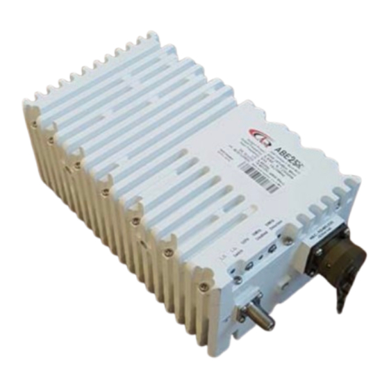
INTRODUCTION The ABE25X is a reliable, high quality, cost efficient stand-alone block up converter. The application for this block up converter is X-Band VSAT communication in an outdoor environment. This line of superior products, engineered using state of the art technology, is characterized by unparalleled durability and dependability. -
Page 6: Receiving And Inspection
Identify, in writing, the condition of the equipment, Refer to the Invoice, Purchase Order and the date the equipment was received. Notify Actox Corporation RMA department of the equipment condition and obtain a Return Material Authorization (RMA) number and shipping instructions. -
Page 7: Preparing For Installation
Preparing for Installation Before attempting to install or use the block up converter, we recommend that you first familiarize yourself with the product by reading through this manual. Understanding the operation of the system will reduce the possibility of incorrect installation, thereby causing damage or injury to yourself or others. The block up converter must be installed in accordance with the conditions and recommendations contained in the following sections. -
Page 8: General Description
Band. The block up converter can be used as a stand-alone unit or in a redundant configuration. Specifications Table 1 summarizes the specifications of the ABE25X BUC. For mechanical specifications, refer to the outline drawing, Appendix 1. General Considerations The block up converter shall meet all specifications over full bandwidth and under all environmental conditions when terminated with a load of VSWR at 2:1 unless otherwise specified. -
Page 9: Installing The Block Up Converter
Installing the Block-Up Converter Tools and Test Equipment Have on hand a standard electrician's tool kit and any tools listed in the antenna manufacturer's installation instructions. Site Considerations The BUC is designed to mount on the antenna. Locate and install the antenna according to instructions supplied by the antenna manufacturer. - Page 10 LED Indication STATUS LED Power OK, L.O unlocked GREEN L.O locked and amplifier functioning normally 10MHz LED No 10MHz reference detected GREEN 10MHz reference detected within requirement Connectors' Pin Assignment Connector Type Pin # Signal Parameter J1 "IF IN" IF Input -0 dBm, max F-type female 10 MHz...
- Page 11 INTERFACE_19PIN Connector X1 (19 pin) Signal type Signal Name Description Ethernet RX_P Ethernet RX_N Ethernet TX_P Ethernet TX_N RS-422/485 TX_B - RS-422/485 TX_A + RS-422/485 RX_B - RS-422/485 RX_A + RS-422/485/232 GND RS_GND RS-232 TX_RS-232 RS-232 RX_RS-232 Control - TTL /MUTE_IN To Mute short Pin M &...
- Page 12 Bias T (for example, ABT6ARN/ABT6ARF manufactured by Actox Corporation) or a similar bias T type. Please make sure to check the sticker on the BUC for the appropriate power source before any power connections are performed.
-
Page 13: Recommended Test Equipment
Recommended Test Equipment The following equipment or equivalent is recommended for installation and system alignment: Equipment Type Spectrum Analyzer HP8563E Digital Voltmeter Fluke 8050 Adapter Waveguide to coax C or Ku-band RF cables With calibrated insertion loss up to 15GHz 40 dB attenuator High Power to match HPA output. -
Page 14: Technical Specifications
Table 1 Specification TECHNICAL SPECIFICATIONS RF frequency 7.9 to 8.4 GHz Local oscillator 6.95 GHz IF frequency 950 to 1,450 MHz Output power 25W (+43.9 dBm min.) IF connector N-type or F-type (field-exchangeable) Power supply - auto-ranging +15 ~ +60 VDC via IF Connector, 87 W max Output interface CPR-112G, CPR-137G, WR-90G, WR-112G Gain... -
Page 15: Assembly And Installation
Connections and Mounting Hardware The IF input connection requires a coaxial cable with an F or N type connector. The RF output requires a waveguide with a CPR-112G, CPR-137G, WR-90G, WR-112G flat flange. An O-ring shall be used to seal the waveguide connection. Assembly and Installation Use the information in this section as a guide to assemble and install the block up converter. -
Page 16: Functional Overview
Functional Overview General This section describes the block up converter functions in detail. The functional overview explains the RF amplification, monitor & control and power distribution. IF/RF Conversion and Amplification The IF Input requires a signal with a 10MHz reference, and +15 ~ +60 VDC power source. 2-4.5Amps nominal enters the BUC by a coaxial cable, converted to X-Band by the BUC and goes through an internal isolator and reject filter, which provides a good VSWR at the input. -
Page 17: Procedure
Operation It shall be performed by authorized personnel prior to maintenance and/or repair. Procedure Verify that the installation procedure described was completed. A complete physical check of the customer’s system is suggested. The output power available at the output waveguide flange is extremely hazardous. -
Page 18: Maintenance
Maintenance This section contains information on how to maintain, troubleshoot and repair the block up converter. The block up converter is extremely reliable, requiring very little preventive maintenance, or repair. Should there be a malfunction, this section also contains technical information to help diagnose basic failures. Preventive Maintenance Shut down the block up converter before disassembly and remove all cables and connectors. -
Page 19: Performance Check
A non-warranty and out-of-warranty repair service is available from Actox Corporation for a nominal charge. The customer is responsible for paying the cost of shipping the BUC both to and from Actox Corporation for these repairs. Page 19 of 36... -
Page 20: Appendix 1 Mechanical Drawing
Appendix 1 Mechanical Drawing Page 20 of 36... -
Page 21: Appendix 2 Spare Parts Order Form
Email: mark_moore@actox.com For additional information, please contact our customer service department at: (619)906-8893 or 1-866-888-6087 Actox Corporation designers and manufacturers of telecom & wireless products Spare Parts Order Form ABE25X X-Band BUC From: Place By: Signature: Telephone: Email: Part Description... -
Page 22: Appendix 3 M&C Commands
Appendix 3 M&C Commands Reply Packet format Explanation Interpretation Examples 7E FX E0 ZZ 7F Acknowledge that the X = Device address of the packet 1) reply: 7E FF E0 E0 ACK (Acknowledge received packet was source device. properly processed. ZZ = CRC. - Page 23 1) cmd: 7E FF 02 18 FE E4 reply: 7E FF 84 18 FE 00 C8 AA 7F 7E FF 02 Query device for AA AA = Attenuation in 10 (Atten = 0x00C8 = 0d200 = Update Attenuation: 18 FE E4 current attenuation 7E FF 84 18 FE GG x dB.
- Page 24 alarm is clear) 1) cmd: 7E FF 02 00 0F 0D 7F reply: 7E FF 84 00 0F 00 01 8A 7F 7E FF 02 XX = Alarm state (0 = Update summary Query device for (Summary alarm is raised) 2) cmd: Get Summary 00 0F 0D alarm: 7E FF 84 00 0F...
- Page 25 M&C Serial Protocol. SCI Packet Byte Description ♦ STX is the start transmission byte (defined as 0x7E). This byte is used to determine the start of a packet. ♦ Dest/Src Address contains the destination address in the high nibble and the source address in the low nibble.
- Page 26 CRC Calculation Example To send a command to read the temperature (database element = 0x0606) from the Booster (device address 0x0F), the command is: Example Only --------------------------------------------------------------------------------- 7E FF 02 06 06 02 7F Dest/Src = 0xFF CMD/Len = 0x02 1111 1111 0000 0010 = 1111 1101...
-
Page 27: M&C Connection Instructions
Appendix 4 BUC 19 pin connector for a PC / Laptop BUC connection to PC carried by cable with 19 pin female connector (fig.1) on the one side and RJ45 (fig. 2), two DB9 (fig. 3) female connectors: RS232 and RS485 on the other side. Figure 1.1 — 19 pin connector configuration Figure 1.2 —... - Page 28 Ethernet RX_P RX_N TX_P TX_N RS-485 GNDISO TX_B TX_A RX_B RX_A RS-232 GNDISO TX_RS-232 RX_RS-232 MUTE_IN ALARM_IN P_OUT_OUT GNDISO Table 1 — BUC to PC Cable Connection Page 28 of 36...
- Page 29 BUC User Manual via PC Run NewBuc v.301 on your PC, when it opened you will see next window: Figure 2.1 — Start window with Monitor Tab In the head there is device information, such as: Device Name: Name that you can give to your device (You can change device name in the tab Settings) ...
- Page 30 Attenuation: Configurable parameter. Controls gain attenuation. For change attenuation lever (from 0 db to 20 db) fill new value in the field and click button Set to apply changes. MUTE: Configurable parameter. Stand-by BUC (On/Off output transmit). Includes two modes: Mute – output transmitter will be shut down until demand; Unmute –...
- Page 31 HPA Temp — indicates red if device hot spot as exceeded 85°C or green if it lower. Figure 2.3 — Program Address Configurations Settings Tab Tab Settings open access to change BUC configurations. The tab indicated on the fig. 2.4 Figure 2.4 —...
- Page 32 BUC Address Configuration: Displays current BUC address. Button Read allows find out current address. Additional BUC Options: Device Name: Let you rename your device; Description: Write here description or notes about your device; Start Mute: Option that lets you to start BUC muted. Configurable. Factory default, disable.
- Page 33 BUC User Manual via Ethernet For connection with BUC via Web use internet browser. You will see next page: Figure 3.1 — Start Page For log in type your login and password in appropriate fields. There are two access levels: User and Admin. By default User`s access level ID: Login: 1234;...
- Page 34 Figure 3.2 — Monitor Tab In the head of the page you will find information about your device (BUC Name, Model and Serial Number) and current access level (User or Admin). On the tab Monitor situated BUC telemetry and BUC Alarms. Tab Monitor is functionally similar to the tab Monitor from the program NewBuc v.301 (see fig.
- Page 35 Figure 3.4 — Settings Panel (Access Level: User) This tab conditionally divided into two panels. Left panel contains information about current connection parameters (DHCP status, IP Address, Subnet Mask, Default Gateway, Port and MAC Address), connection speed (for RS232 and RS485 ports) and BUC address. Right panel designed to change login configurations, such as Name and Password.
- Page 36 in the green field and push the button Set. To apply changes you must reboot your device! New Community: you can set password for SNMP browser. Without this password you wouldn`t get access to BUC via SNMP browser. Type new password in the green field.
Need help?
Do you have a question about the ABE25X and is the answer not in the manual?
Questions and answers