Advertisement
Getting Started

- This logger must be used in accordance with the information provided in this manual.
- This equipment contains a lithium battery. Do not cut open, incinerate, recharge or expose to temperatures in excess of 100°C (212°F). Danger of explosion if the battery is incorrectly fitted.
- The battery should only be replaced with the battery type specified in this document, observing the correct polarity.
- This equipment should only be connected to a computer using a CAB-0007- USB interface cable.
- This equipment should be used within the temperature range and other environmental conditions specified in this manual.
To use a Tinytag Ultra 2 thermocouple data logger you will require the following items:
- copy of the Tinytag Explorer software
- CAB-0007-USB download cable
Install Tinytag Explorer and the USB download cable, as described in the software's quick start guide and plug the USB cable into the socket on the front of the logger.
For further information on how to start the data logger recording and how to view the results from the unit, please see the Tinytag Explorer quick start guide.
Thermocouple Specific Configuration Options in Tinytag Explorer
When starting a thermocouple data logger in Tinytag Explorer you will see two options specific to this type of logger that are not mentioned in the software's quick start guide.
Thermocouple Type
Select the thermocouple type you are using from the options listed.

If you are unsure what type of thermocouple you have, the plug or cable on it may be coloured coded and you can match this to the diagram next to each option.
Colours for the different types of thermocouple are as follows:

Burnout Response
The burnout response option allows you to tell the data logger what to do in the event of a problem with the thermocouple being used.

If a faulty thermocouple is attached to the data logger it is possible for the logger to show readings that may appear to be correct. The burnout response can deliberately drive readings low or high in the event of a problem, to make it clear to the user that there is a problem.
Choose what you want the data logger to do from the options listed.
Using the Thermocouple Data Logger
To get the best results, ensure that the data logger and the thermocouple plug have sufficient time to reach the same temperature before recording begins. If the thermocouple has been stored at a significantly different temperature from the logger, allow 30 minutes for stabilisation.
It is advisable to keep the logger at a constant temperature whilst recording, and to avoid large temperature gradients across the unit (for example, avoid placing the logger on a very hot or very cold surface).
Large fluctuations in logger temperature can cause temporary errors in the probe measurement, although these are unlikely to exceed 1°C.
Measurement Specification
Thermocouple
| Sensor Type | Type K, J, T or N Thermocouple |
| Range | |
| Type K | -270 to +1370°C (-454 to 2498°F) |
| Type J | -210 to +1200°C (-346 to 2192°F) |
| Type T | -270 to +400°C (-454 to 752°F) |
| Type N | -270 to +1300°C (-454 to 2372°F) |
| Reading Resolution | 0.01°C |
| Cold Junction Compensation | -10 to +70°C |
| Accuracy | Better than ±1.0°C across all thermocouple ranges when the logger is between -10 & +70°C. |
Note: The above accuracy figures do not include the thermocouple probe.
Logger Temperature
| Range | -40 to +85°C (-40 to +185°F) |
| Sensor Type | 10K NTC Thermistor |
| Response Time | 20 mins to 90% FSD in moving air |
| Reading Resolution | 0.02°C or better |
| Accuracy | Better than ±0.5°C |
Physical Specification
| Logger | |
| IP Rating | IP51 |
| Working Temperature Range | -40 to +85°C (-40 to +185°F) |
| Case Dimensions Height Width Depth | 42mm / 2.83" 60mm / 2.36" 33mm / 1.30" |
| Weight | 65g / 2.29oz |
| Supplied Type K Thermocouple | |
| Temperature Range | -100 to +250°C (-148 to 482°F) |
| Lead length | 1m / 39.37" |
Battery Information
The battery fitted in this product is a single cell containing less that 1g of lithium and meets the requirements of the UN Manual of Tests and Criteria, Part III, Subsection 38.3.
| Recommended Battery Types | SAFT LS14250, Tekcell SBAA02P or Eve ER14250 |
The logger will operate with other ½AA 3.6V Lithium batteries but performance cannot be guaranteed.
| Replacement Interval | Annually |
Before replacing the battery the data logger must be stopped.
Data stored on the logger will be retained after a battery is replaced.
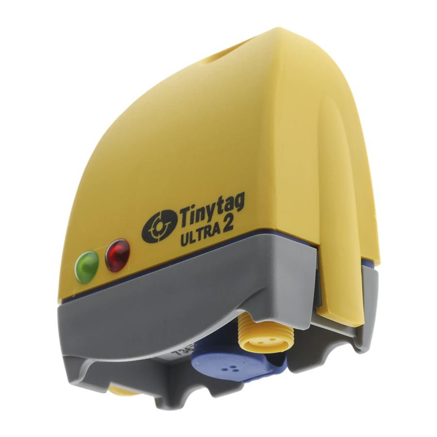
LED Flash Patterns
When logging, status LEDs on the front of the logger will flash as follows:
| Flash Pattern | Indication |
| A green flash every 4 seconds | Logging |
| A green flash every 8 seconds | Waiting to log (set for a delayed start) |
| A red flash every 4 seconds | Alarm limit breached |
For more information on the alarms and how they work, please see the Tinytag Explorer quick start guide and help file.
Notes
If used at low temperatures the data logger should be allowed to warm to room temperature before it is opened to avoid condensation forming inside it.
The IP51 rating is valid only when the logger's connector cover is fitted and the unit is orientated with it's hanging tab uppermost.
Trigger Start
The trigger start option allows a logger to be set up as required and then started at a later time with a magnet. The position of the trigger start switch is indicated by the • • • marking on the back of the logger. When the "Wait until trigger event" option is selected in the Tinytag Explorer software the green LED on the logger will flash once every eight seconds to indicate that it is waiting to start. When a magnet is swiped past the • • • marking, the green LED will light to indicate the switch is closed. After the magnet has been removed, the green LED will flash every four seconds to indicate that the logger is recording.
Calibration
This logger is configured to meet Gemini's quoted specification during its manufacture.
We recommend that the calibration of the logger should be checked annually against a calibrated reference meter.
A certificate of calibration, traceable to national standards, can be supplied for an additional charge either at the point of purchase, or if the logger is returned for a service calibration.
Approvals
Gemini Data Loggers (UK) Ltd. operates a Business Management System which conforms to ISO 9001 and ISO 14001.

Further Information
Further information on Tinytag data loggers, software and accessories can be found on our web site at: www.tinytag.info
If you should have any further questions, please contact your distributor or:
Gemini Technical Support
t: +44 (0)1243 813009
e: help@tinytag.info sales@tinytag.info

Documents / Resources
References
Download manual
Here you can download full pdf version of manual, it may contain additional safety instructions, warranty information, FCC rules, etc.
Advertisement


Need help?
Do you have a question about the Ultra 2 and is the answer not in the manual?
Questions and answers