
Related Manuals for S.E. International URSA II


Summary of Contents for S.E. International URSA II
- Page 1 OPERATION MANUAL INTERNATIONAL ® ® ® S.E. International, Inc. P.O. Box 39, 436 Farm Rd. Summertown, TN 38483 USA 1.800.293.5759 | 1.931.964.3561 | Fax: 1.931.964.3564 www.seintl.com | radiationinfo@seintl.com...
-
Page 2: Table Of Contents
Contents Introduction..............................4 URSA-II MCA Minimum System Requirements.....................4 URSA-II Technical Specification ..........................4 Hardware Description and Controls ......................4 Front End Panel ................................4 Back End Panel................................5 Battery Compartment ..............................5 Powering the URSA-II............................5 AC Power Supply .................................5 Charging the Internal NiMH Batteries ..........................5 Using Alkaline Batteries ...............................5 Alternate External Power..............................5 Starting URSA-II for the First Time ........................6 Initial Startup Steps ..............................6... - Page 3 Threshold................................25 Coarse Gain and Fine Gain..........................25 Shaping Time..............................25 Determining Initial Hardware Settings........................25 Performing an Energy Calibration ..........................26 Performing a Shape Calibration ..........................28 Creating a Regions of Interest (ROI) Set ........................29 Manually Creating or Editing an ROI Set (“Manual Method”)................30 Performing an Efficiency Calibration ..........................31 Fine Tuning Hardware Settings..........................32 Service................................33 Software License Agreement .............................33...
-
Page 4: Introduction
Introduction Thank you for purchasing a URSA-II (Universal Radiation Spectrum Analyzer-II). A lot of time and effort was spent trying to make the URSA-II hardware, software, and this manual as user-friendly and error-free as possible, but we cannot guarantee that no mistakes or omissions are present. All software (and manuals, for that matter) are “works-inprogress,”... -
Page 5: Back End Panel
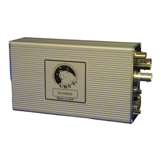
8. DIN connector. This provides plus and minus 12-volt power if needed for detector preamplifiers. Also provides plus 5 volts as well as logical outputs coupled to ALARM0 and ALARM1 in the URSA-II MCA software. 9. S9- High Voltage C connector his provides high voltage and accepts coupled signal for INPUT1. Back End Panel 1. -
Page 6: Starting Ursa-Ii For The First Time
The center pin of the External Power Input is positive. Incorrectly applying voltage to the URSA-II will likely damage it. Starting URSA-II for the First Time The URSA-II hardware and MCA software are designed to connect URSA-II to a computer as painless as possible. -
Page 7: Functions, Controls And Displays
“Yes” to enable the high voltage to the displayed value or “No” to start URSAII MCA with the high voltage turned off. It is recommended that you enable the high voltage at this time unless you have some reason to believe that enabling the high voltage to the value displayed might damage the detector (e.g., the HV is higher than you think it should be or you don’t actually have the detector connected yet). -
Page 8: Utility Menu
Menu Bar Button Bar Hardware Status Bar New User Hints Bar Aquisition Controls and Indicators Spectrum Spectrum Display Smoothing Button Panel Spectrum Status Bar Note: If a saved spectrum is loaded to “live,” any spectrum currently displayed will be lost without warning unless you explicitly save it before loading the saved spectrum. -
Page 9: Alarms
the high voltage to the detector (when HV is disabled, the menu item will read “Enable High Voltage). “Detector…” opens a sub-menu containing various utilities for working with detectors. “Add…” allows new detectors to be added in the same manner as during URSA-II MCA startup, without the need to shut down and re-start URSA-II MCA. -
Page 10: Misc
“Show Alarm Window…” opens the same window that is automatically opened when any alarm condition occurs. Misc This menu item is for special functions that do not easily fit into other categories. All of these item shave been suggested or requested by users. “Collect Multiple Sequential Spectra”... -
Page 11: Sound
Spectrum Status Bar will display the ROI name and number of total counts for the ROI currently under the cursor. If “Spectrum Quick Grow” is checked, the left axis of the spectrum display will be set to a minimal value when the spectrum is cleared. -
Page 12: Help
running. Functionally, this is identical to copying all of the files contained in the “CalFiles” subdirectory onto a floppy disk. Help The “Help…” menu item opens the URSA-II MCA Help file. (Note: The Help file has not yet been distributed as of URSA-II MCA version 2.0.1) The “URSA-II Support Website”... -
Page 13: New User Hints Bar
on opening of URSA-II MCA, at the start of each acquisition, and about every second or two during an acquisition. This value is not updated at any other time, i.e. when the URSA-II is sitting idle. If the voltage drops below 10 V a warning will be displayed, and at 9.5 V a message will be shown that the battery condition is now critical and batteries should be replaced immediately. -
Page 14: Acquisition Controls And Indicators
is loaded and “Show ROIs” is checked under the “View” menu. If no ROI set is loaded, “Show ROIs” is not checked, or the cursoris not over an ROI, these boxes will be blank. The first of these two displays the name given to the ROI, and the second shows the total (integrated) number of counts in that ROI. -
Page 15: Spectrum Smoothing
spectral analysis performed. Moving downward, the next object is the white “Time (sec)” input box, with a checkbox immediately to its left. If thecheckbox is checked, URSA-II will stop acquiring a spectrum when the total counting time equals this value. Time units are in seconds. An acquisition cannot be started or continued if the checkbox is checked and the acquisition time equals or exceeds the amount of time in the input box. -
Page 16: Roi Panel
where signal and high voltage are carried on the same line. Input 2 is the separate connectors for signal and high voltage, BNC and SHV respectively. If “Shaped Input, Positive Polarity” is used, either of the inputs can be used. Note: If a shaped input is used, Coarse and Fine Gain controls will have no effect on the spectrum input. Also, take care to ensure that shaped pulses are kept in the 0 to 5V range;... - Page 17 above) that flags the fact that the current ROI set has been altered but not yet been saved. The small panel (“Drag cursor to”) immediately below this normally has “Zoom (normal)” checked. This means that clicking and dragging on the spectrum will have the normal effect of zooming and un-zooming the display. If “Set ROI”...
-
Page 18: Efficiency
The “Cancel” button will only be enabled when the current ROI set has been altered or edited in any way since it was last saved. Using this function will re-load the current ROI set as it was last saved. The “New ROI Set” button clears the current ROI set from URSA-II MCA (if it has not been saved, you will be given the opportunity to do this first) so that a new ROI set can be created. -
Page 19: Peak-Based
Enter the activity of the specific isotope in the “Activity” input box. This must be performed for all ROIs within the ROI set prior to performing an efficiency calibration. Use the “Units” dropdown list to assign units to the activity. Note: The activity units must be the same for all activities entered. Changing the units for one specific ROI will change the units assigned to all other ROIs within the ROI set. -
Page 20: Roi-Based
found peaks and convert them to an ROI set. The “Peak Search Sensitivity” control affects how “distinct” a peak needs to be before it is flagged as “found.” If it appears that to many peaks have been identified in a peak search, try lowering this value. And vice-versa… The four radio buttons determine what which method is used in identifying the nuclide associated with a peak. -
Page 21: The "Print Preview" Or "Report" Screen
The “Sample Description” input box allows the entry of a brief description or note. This will be displayed in all subsequent analyses and reports generated, and will be saved with the spectrum file. If “Use Sample Quantity” is checked, two controls will be enabled that allow entry of a sample quantity and associated units. -
Page 22: Using The Library Editor
The “-” and “+” magnifying glasses, along with the slider, allow the size or zoom of the report display to be changed. The “Return” button closes the report window. Using the Library Editor Two libraries are distributed with URSA-II MCA, “UrsaLib” and UrsaLib Full. As a general rule, UrsaLib is intended for NaI(Tl) detectors, and UrsaLib Full is intended for detectors with higher resolution. - Page 23 Only enabled isotopes will be available in URSA-II MCA. Use the “Save Lib.” button to save the library as it exists, reflecting any changes that have been made. This can also be used to save the library under a different name. The “Cancel”...
-
Page 24: Using Mcs Mode
Pri. This column of radio buttons is used to indicate which energy is designated as the “primary peak” for the isotope. The primary peak MUST be present in a spectrum (in addition to the secondary peak) in order to positively identify the isotope, and activity will be calculated based in the primary peak. -
Page 25: View Menu
option is used with high count rates. View Menu “Show New User Hints” enables/disables the New User Hints Bar, which displays a sentence or two briefly describing the function for any display or control the mouse cursor is currently over. Disabling (i.e., unchecking) this menu item hides the New User Hints Bar, making the Spectrum Display slightly larger. -
Page 26: Mcs Acquisition Controls And Indicators
The “About…” function opens a window containing information about URSA-II MCA and the URSAII hardware. “Version Information…” simply displays the version number of the URSA-II MCA software. MCS Acquisition Controls and Indicators The four buttons along the top of this section control the acquisition of spectra. From left to right, these are “Start,”... -
Page 27: Procedures
If “Alarm at:” is checked, the analog display will turn red and an audible indicator will be played if the count rate exceeds the value contained in the input box. The alarm will reset when the count rate falls below the alarm level, or when the box is unchecked. -
Page 28: Radiation Source And Detector
Fortunately, this process is neither difficult nor time consuming. The process for determining appropriate hardware settings consists of placing a known radiation source of modest activity in front of the detector, adjusting one or more of the hardware settings, and beginning an acquisition. -
Page 29: Threshold
With scintillation detectors the bias voltage also provides gain, so essentially the same spectrum can be obtained using a lower bias voltage and higher gain or a higher bias voltage and a lower gain. If the bias voltage is higher than optimal, the spectrum will appear distorted. Threshold The threshold, sometimes called input sensitivity or discrimination, is the minimum pulse height in millivolts (mV) that will be recorded by URSA-II as a count. - Page 30 Generally speaking, most adjustments to expand the separation between peaks should be performed using the HV adjust. Start increasing the gain only if the peak separation remains too small even at the maximum HV recommended for the particular detector; increase the gain until the peak separation is slightly wider than wanted, then reduce the HV as needed.
-
Page 31: Performing An Energy Calibration
14. If both 137Cs peaks are visible, but are closer together than wanted, increase the HV and go back to step 4. 15. If the HV is at the highest HV recommended by the detector manufacturer (or if it is higher than you are comfortable with or is obviously distorting the spectrum), leave the HV where it is, increase the overall gain and go back to step 4. - Page 32 advantages to using this method, especially in the low-energy range. In short, the more data points entered, the more accurate the energy calibration will be. If there is a limited energy region in which you are interested, adding additional data points in those areas will increase the accuracy in that area without skewing the energy calibration in other regions of the spectrum.
-
Page 33: Performing A Shape Calibration
the status bar. 5. Acquire additional spectra and add additional energy calibration data points as desired. When finished, click the “Close” button to hide the energy calibration window. Performing a Shape Calibration Prerequisites This procedure assumes that the detector is attached to the URSA-II, the URSA-II is switched on, the URSA- II MCA software has been successfully started, a radioactive source of known isotopic composition is on the detector, URSA-II hardware settings have been set appropriately, and an energy calibration has been performed. -
Page 34: Creating A Regions Of Interest (Roi) Set
centroid of the peak as well as calculate and display the FWHM multiplier. Two additional red lines will also be displayed estimating the bounds of the peak area. 4. Use the group of four buttons to adjust the outer red lines to accurately reflect the boundaries of the peak. 5. -
Page 35: Manually Creating Or Editing An Roi Set ("Manual Method")
4. The found peaks can now be edited, if desired, by clicking on the “Allow Edit” box. The user can now adjust the centroid and the left and right edges of each peak region. Peaks can also be added as well as deleted. a. -
Page 36: Performing An Efficiency Calibration
2. Click on “ROI Panel” on the URSA-II button panel. This will open the ROI edit settings panel along the bottom of the spectrum display. 3. To create a new ROI set, click on the “New ROI Set” button to assign a file name to the new set. (If this is not done before the following steps, a “Not Saved!”... - Page 37 Note that the ROI set can contain isotopes that are not included in the efficiency calibration source. These must be designated as “unknowns,” however, so that URSA-II MCA knows to calculate efficiencies for these ROIs from interpolated data. The perfect efficiency calibration source matches exactly the type of samples you will be quantifying in isotopic composition, activity, and physical makeup.
-
Page 38: Fine Tuning Hardware Settings
CAUTION: Do not send a contaminated instrument for repair or calibration under any circumstances. There are no serviceable parts inside the instrument. If the URSA II requires servicing, please contact your distributor or the manufacturer at the following address: S.E. International, Inc. - Page 39 This is a legal agreement between you and Paul R. Steinmeyer as well as Radiation Safety Associates, Inc. (collectively “RSA”), the owners of the URSA II Hardware and computer program that accompanies this license agreement (the “Software”). BY INSTALLING THE SOFTWARE YOU SIGNIFY THAT YOU AGREE TO BE LEGALLY BOUND BY THE TERMS AND CONDITIONS OF THIS LICENSE AGREEMENT.
-
Page 40: Hardware Warranty
PROCEDURE FOR OBTAINING PERFORMANCE OF WARRANTY: In the event that the product does not conform to thiswarranty, please write or call to the address above. S.E. International, Inc. will not accept contaminated instruments for calibration or repair under warranty or otherwise. - Page 41 Please fill out this form and send it back to us if you would like to be notified of the NIST calibration renewal for your instrument to: S.E. International, Inc. P.O. Box 39, 436 Farm Rd. Summertown, TN 38483 1.800.293.5759 | 1 931.964.3561 | Fax: 1.931.964.3564 www.seintl.com | radiationinfo@seintl.com...
Need help?
Do you have a question about the URSA II and is the answer not in the manual?
Questions and answers