
Related Manuals for Abelko IMSE UltraBase20


Summary of Contents for Abelko IMSE UltraBase20
- Page 1 IMSE Ultra User manual UltraBase20 UltraBase30 UltraBase40 Valid for release 1.92.X 2023‑05‑22 www.abelko.se...
-
Page 2: Table Of Contents
Contents 1 Introduction Other Manuals ........Warranty . - Page 3 6.3.2 Selection of time period ......6.3.3 Logs ......... Zoom and pan .
- Page 4 8.5.3 Create an automatic system backup to SD card ....8.5.4 Front panel buttons for SD‑card on UltraBase30 ....Update .
- Page 5 All information in this manual is based on information available at the time of printing. The manual is published to ease the use of an Ultra. Abelko Innovation cannot guarantee that there are no mistakes or errors in this documentation and cannot be held responsible for any consequences resulting from the use or misuse based on this information.
-
Page 6: Introduction
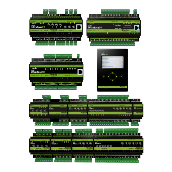
1 Introduction Welcome to IMSE Ultra. This series of products consists of the control units IMSE UltraBase20, IMSE UltraBase30 and IMSE UltraBase40, operator panel IMSE Ultra OP and expansion modules that can be connected to expand the number of inputs and outputs. -
Page 7: Other Manuals
60 months of the veri‑ fied delivery date. The purchaser is responsible for removal, re‑installation and for paying trans‑ port costs to Abelko, and Abelko will repair the defect and return the equipment free of charge to the purchaser. - Page 8 © Abelko Innovation 2022...
-
Page 9: Overview Of The Device
2 Overview of the device IMSE UltraBase is a general device for controlling and monitoring buildings, systems or facilities. It is configured to do a certain task and connects to sensors, actuators and other devices. This manual requires that the device is configured and installed in a facility. The device’s user interface is web‑based, which means that the device is available through a web browser. -
Page 10: Menus
of interest or make settings using these overviews and summaries. If there are no overviews or sum‑ maries, the list of active alarms will appear on the homepage. Under the menu System and Settings you can choose what you want to see at the homepage. There are four buttons up in the interface: The bell indicates if there are any active alarms in the system, the icon with multiple bells indicates if there are any active alarms for any companions and the letter shows if there are any new notes. - Page 11 ‑ Email ‑ Recipients ‑—————————‑ ‑ Modbus slave register ‑ Modbus slave settings ‑ Modbus TCP Gateway ‑—————————‑ ‑ RS485 Ex settings ‑—————————‑ ‑ External units sendouts ‑ Portal update ‑ Companion Configuration ‑ Graphical programming ‑ Summaries ‑ Overviews ‑—————————‑...
-
Page 12: Menus Limited View
Help ‑ Manuals ‑ Support 2.2 Menus limited view A user can have limited view of the web pages, which means that not all menus are visible. To temporarily leave this mode, go to the menu Help and Support. Under Limited view, you can enable/disable the limited view temporarily by using the check box, and then click Set. -
Page 13: Connect A Pc Directly To Imse Ultrabase
2.3 Connect a PC directly to IMSE UltraBase If your Ultra is not connected to a network you have access to, you can connect a computer di‑ rectly to the Ultra. On the front, to the right, there is an Ethernet port labelled LOCAL PC. It can be used to connect a network cable directly to your computer. -
Page 14: Overviews
3 Overviews Overviews are pictures created of an installation with important values so you can quickly and easily see the status of the installation. This chapter will explain how overviews work and how they can be used. 3.1 How To Use An overview provides a schematic image of a system since it can be customized to how your installa‑... - Page 15 Click on a resource to change settings, see alarm limits and more depending on resource type. If you want to change the start page go to the menu System, Settings.
-
Page 16: Summaries
4 Summaries Summaries are menu pages with added resources to see and edit, such as channels, parameters, alarms and more. Summaries are created by the person who configured the system. This chapter will explain how the different resources look like in a summary and how they work. 4.1 Channels Channels handle all the variable data in the unit and have different view alternatives. -
Page 17: Parameters
4.2 Parameters Parameters are used to store settings and can be both editable and non‑editable. If they are editable you can set their values. 4.3 Alarms Alarms will help you monitor channel values. You can see its name and current status. If the alarm is active, click on it to go to the active alarm list where you can acknowledge it if needed. -
Page 18: Time Schedules
4.4 Time schedules A time schedule is used to set times when things should be active or inactive. Edit will take you to the timeschedule’s settings. You can see the time schedule’s current status on the top of the page. To disable a schedule uncheck the box to the left of its name. -
Page 19: Date
• If the rule enables objects and is currently active, the light shines green. • If the rule disables objects and is currently active, the light shines red. • If the rule is not active, it will be grey regardless if it enables or disables objects. You can delete a rule or disable it with the box under Type. -
Page 20: Weekly
4.4.2 Weekly This is used when you want something to be repeated every week. 1. Select if you want the rule to enable (On) or disable (Off) objects. 2. Set start and stop time by moving the bar in the time axis or type the time in the boxes. 3. -
Page 21: Yearly
2. Set start and stop time by moving the bar in the time axis or type the time in the boxes. 3. Mark the date in the calendar. The rule will automatically be set to Active. You can Inactivate it by using the checkbox up in the corner. - Page 22 1. Select if you want the rule to enable (On) or disable (Off) object. 2. Set start and stop time by moving the bar in the time axis or type the time in the boxes. 3. Mark the date in the calendar. The rule will automatically be set to Active.
-
Page 23: Periodically
4.4.5 Periodically This is used when you want something to be repeated a certain period. 1. Select if you want the rule to enable (On) or disable (Off) objects. 2. Set Period time, this will decide how often the period should be repeated. For example, if you want something to be repeated every third day, type 3 under Day. - Page 24 In this example you can see how the outdoor temperature (x‑axis) affects the set value for the flow temperature (y‑axis). For example, you can see that when the outdoor temperature reaches 0 °C, the flow temperature should be 40 °C. Click Edit to change settings.
-
Page 25: Alarms
5 Alarms This chapter will explain how alarms and alarm history are viewed. It will also explain the different types of alarms, how to acknowledge alarms and how to change the settings for alarm sendouts. 5.1 Active Alarm All active alarms in the system are listed on Active alarms. Click Acknowledge to acknowledge an alarm with your name. -
Page 26: Alarm History
5.2 Alarm History Here, all the alarm events are listed. You can see when they were activated, inactivated and acknowl‑ edged. A‑alarms are red, B‑alarms are yellow and C‑Z alarms are blue. When an alarm is inactivated, it will turn green. Click on an alarm to get more detailed information about the alarm. - Page 27 • B‑alarm (yellow indication) • In addition to these, an alarm can have the priority C‑Z (blue indicator) In addition to these types, there are events/errors and messages. Events/errors are created by the system and provide information when there is an error in the system, preventing from working prop‑ erly.
-
Page 28: Alarm List
someone has noticed the alarm. Details of the reset and the acknowledgment are both recorded in the alarm history. • Automatic reset, without acknowledgment: there is no need for a user to acknowledge the alarm. The alarm is cleared when the error is no longer active as defined in the alarm conditions. You can specify delay and hysteresis values in the condition. - Page 29 Create a new alarm group 1. Click New alarm group. 2. Name the alarm group. 3. Then choose Language for the mail sendouts and under Type you can choose which format the mails should have. You can also create your own format. 4.
-
Page 30: Alarm Sendouts
6. Click Save. Email settings for sendouts are configured under the menu Alarm, Alarm sendouts. 5.6 Alarm Sendouts Here you create and edit alarm sendouts. Alarm groups must be created before editing alarm send‑ outs (see previous chapter). - Page 31 Add a recipient 1. Click on the icon under Recipients on the alarm group you want to add to. 2. Select an already existing recipient (these are created under the menu Communication, Send‑ outs) in the drop down menu or create a new by entering name and contact information. Mail host is mandatory since all email recipients need to be tied to an email server.
- Page 32 3. Click Add. The system will send an email to all recipients each time an alarm in the alarm group turns active or inactive. The mail contains information about the alarm event. The mail can either be sent to people or to an alarm server.
-
Page 33: Logging Data
6 Logging data Logs are history of what has happened in the system, and are used to create statistics. This chapter will explain how to create and edit logs. Logs are created under channel settings both in the graphical programming and under the menu Configuration, Applications &... - Page 34 Type Description Interval Max/Min Each log point consists of the 1s, 2s, 15s, 1min, 5min, 15min, maxor min value since the 1h, 24h, 1 month previous log point. The min‑ and max values are calculated as a rolling average with per second resolution.
-
Page 35: Create Logs
Log area Contents When changed When changed logs 6.2 Create logs 1. Go to a channels settings (in the graphical programming or under the menu Configuration, Applications & resources). 2. Click on Add to add a log. You can have different types of logs for the same channel. 3. -
Page 36: Add A Log To A Plot
Treeview: Displays log points that can be added as logs. Only channels and parameters that have logging enabled can be displayed in data logs. This is done in the settings for each channel. Plot area: The area where plots for the logs are displayed. Controls for retrieving data: Settings that control the time period for which data is displayed. -
Page 37: Selection Of Time Period
example per second logs) can take a long time to load for long time periods. To add a log to an existing Y‑axis, drop it directly on that axis in the plot area. When a log is added to a plot it is also listed under Logs below the plot area. The Y‑axis may use SI‑prefixes when displaying very large and small values. -
Page 38: Zoom And Pan
6.4 Zoom and pan 6.4.1 Zoom with mouse wheel The mouse wheel can be used to zoom in or out in the plot. If the mouse cursor is over the plot area and the mousewheel is scrolled both the X‑ and Y‑axis will be zoomed. If the cursor is over a specific X‑... -
Page 39: Saved Views
6.6 Saved views A saved view saves the current view of one or more logs so that the same view can be opened later. Saved views are also used for log sendouts, see chapter Log Sendouts 6.6.1 Create saved view To save the current view, enter a name for it and click Save. - Page 40 1. Add a new recipient next to the log you want to export. 2. Select an already existing recipient (these are created under the menu Communication, Send‑ outs) in the drop down menu or create a new by entering name and contact information. Mail host is mandatory since all email recipients need to be tied to an email server.
- Page 41 4. When you have the recipients click Edit for a Data log. 5. Set Period time (how often you want it to be sent) and an Offset if needed (how far into the period time you want the transfer to take place). 6.
- Page 42 with units are listed. Under these you can see a timestamp and which value the channel had at that time. There is not always data for each time point for each channel.
-
Page 43: Communication
7 Communication The Communication menu allows access to the systems network configuration, overview of alarm‑ and log sendouts, settings for outgoing mail and modbus settings. 7.1 Network Network allows you to handle network settings for Ethernet and see information about Local PC. Allow unencrypted connection controls wether or not it is possible to connect to the Ultra with un‑... -
Page 44: Mail Host
IP address up in the address bar in order to log in again. Note: IP‑addresses on the 192.168.142.XXX network are reserved for the Local PC port*, and not pos‑ sible to set for the Ethernet port. You can always connect with a PC with a cable directly to the Local PC port to change network set‑ tings if you cannot access the device on the Ethernet port. -
Page 45: Recipients
7.3 Recipients View and edit all the people registered in the system. You can also add new recipients. This section gives you an overview over which alarm and log sendouts the different recipients will receive. You can inactivate a recipient with the box next to the recipient’s name. You can also send a test mail. -
Page 46: Modbus Slave Settings
7.9 Portal Update This is a function that, together with a portal server, such as portal.abelko.se, helps keep track of the unit’s IP address. -
Page 47: Companion
If you have a connection that does not change the address very often, such as fiber or DSL, set a high interval. On our portal portal.abelko.se, you can use the units MAC address, view its current IP address and view when the unit was last connected to the server and updated it. -
Page 48: Showing Alarms
automatically has access to settings in all companions with the same access level. When companions are configured they exchange cryptographic keys in a pairing procedure. After that, both sides can be sure of the identity of the other side when they henceforth connect automatically. The communication is encrypted and is safe to use over public networks. -
Page 50: System
8 System This chapter will explain the note tool and the file manager. You will also learn how to create backups and update the system. 8.1 Notes In Notes, you can create notes and see changes made in the system. If you have made changes in the system that you want the other users to know of, you can create a note about it here. -
Page 51: File Manager
3. When you click save, all users will have a new note to read. Click on a note in order to read the whole note. By clicking Mark all as read the letter symbol for new messages will be turned off for the user who is logged on. -
Page 52: Users
Symbols: upload symbols to use when you create overviews. Communication definitions: upload definitions for external units and expansion modules. Usable definitions are available at script.abelko.se. SD card: If there is an SD card in the front of the UltraBase30, you can see its content here. - Page 53 2. Add a username and a password. 3. Select a user level. 4. Select if Automatic logout shall be active by selecting a timeout. 5. Click Save. User levels User level Description Configurator Has full rights, can configure the whole device, upgrade the software, restore backups, and more.
-
Page 54: Settings
Limited view means that the user can only see the following menus: • Home: Overviews and summaries • Alarm: Active alarms and Alarm history • Data: Data logs • System: Notes and Information • Help: Manuals and Support 8.4 Settings Enter the name and the address of the module under the menus System and Settings. -
Page 55: Backups
8.5 Backups Here you can upload, create, export and restore application backups and system backups. - Page 56 Application backups: an application backup contains all files and settings that determine what the device does. This means all applications in graphical programming, application settings, summaries and overviews, configuration of inputs and outputs, and more. An application backup does not include network settings, logged data, alarm history, and notes. You can use an application backup to reset settings before changes were made or to create a new device with the same function.
-
Page 57: Create A New Application Backup
8.5.1 Create a new application backup 1. Click Create new. 2. Name the backup and add a short description. 3. Click Create new. The backup is saved in the system and is added in the list of existing backups that you can delete, export and restore. -
Page 58: Front Panel Buttons For Sd-Card On Ultrabase30
8.5.4 Front panel buttons for SD‑card on UltraBase30 At the front of an UltraBase30, there are two buttons to interact with the SDcard without using a PC. You can create and restore system backups, and update firmware form a SD.card using these but‑ tons. -
Page 59: Update
The file must be of type .load and may contain a software upgrades, parameter bank scripts and more. A .load file is created by Abelko on request. 1. To run a .load file, hold the LOAD button until the LED flashes green. -
Page 60: Operator Panel
3. You will soon see a new window with update information. 4. When the system has updated everything, you will be able to log in again. 8.7 Operator panel Under the menu System and Operator panel, you can see status of the operator panel (if anyone is installed), edit password and language, and also customize the menus of the operator panel. -
Page 61: Help
9 Help 9.1 Manual The manuals are available at https://www.abelko.se. 9.2 Support Here you can find contact information for support. -
Page 62: The Unit Ultrabase20
10 The unit UltraBase20 1. ETHERNET is used to connect to the network. 2. ANALOG OUT manual override. Turn right to activate manual override and increase the output voltage. When the corresponding yellow LED is lit manual override is active. Turn fully left to deactivate. - Page 63 11. 24VAC is used to power the Ultra with 24 V AC power. Ex OUT is not powered on AC power.
-
Page 64: The Unit Ultrabase30
11 The unit UltraBase30 1. ETHERNET is used to connect to the network. 2. Place for SD card. 3. Ex Out is used to connect to expansions modules. This port can also be configured as an RS485‑ port 4. LOCAL PC is used only for direct connection to a PC with the address https:\192.168.142.1. 5. - Page 65 10. LOAD is used to execute a .load file stored on the SD card. There may only be one .load file on the card. A .load file can contain a software upgrade or other commands that will be executed. 11. LOAD + BACKUP is pressed simultaneously to restore the latest backup stored on the SD‑card.
-
Page 66: The Unit Ultrabase40
12 The unit UltraBase40 1. ETHERNET is used to connect to the network. 2. Ex OUT is used to connect to expansions modules. This port can also be configured as an RS485‑ port. 3. LOCAL PC is used only for direct connection to a PC with address https://192.168.142.1. 4. -
Page 67: Power Supply
(+12V) is used to power the Ultra with 12 V stabilized DC, or as a +12 V output when the Ultra is powered from another port. Ex OUT is not powered on +12V power. 10. 24VAC is used to power the Ultra with 24 V AC power. Ex OUT is not powered on AC power. 11. -
Page 68: Term Definitions
13 Term Definitions Acknowledgment: a confirmation that you have received and noticed an alarm. Alarm: an alarm is always created based on a channel and monitors the channel’s value according to set conditions and limits. A‑alarm has a red indicator and B‑alarm has a yellow indicator. In addition to these, you can choose to give an alarm a priority from C‑Z and they have a blue indication. - Page 69 File manager: tool that uploads files to the Ultra. There are predefined folders including sensor defi‑ nitions, communication definitions and backups. Graphical programming: a tool that creates graphical programs. It enables you tp build up an entire system with all of its functions based on the inputs and outputs of the unit. Holiday catalogue: a function usable when working with time schedules.
- Page 70 Time schedules: used to set when something should be active or inactive. You can add rules that can be repeated weekly, monthly, early or with a free adjustable interval. You can also select not to repeat the rule at all or only set for a specific date. Universal input: inputs that measure different kind of quantities (resistance, current and voltage).
Need help?
Do you have a question about the IMSE UltraBase20 and is the answer not in the manual?
Questions and answers