Table of Contents
Advertisement
Quick Links
Advertisement
Table of Contents

Subscribe to Our Youtube Channel
Related Manuals for Bivocom TR341 Series


Summary of Contents for Bivocom TR341 Series
- Page 1 ® Industrial Cellular WIFI Router TR341 Series User Guide...
-
Page 2: Copyright
Product specifications and information in this document are subject to change without any notice, and BIVOCOM reserves the right to improve and change this user guide at any time. Users should take full responsibility for their application of products, and Xiamen Bivocom Technologies Co., Ltd. -
Page 3: About This Guide
About This Guide Thank you for choosing Bivocom Industrial Cellular Router TR341 Series. Please thoroughly read this user guide before you configure and install the device. This manual is compatible with below models Model Description TR341-W Industrial WCDMA ROUTER TR341-LF... -
Page 4: Table Of Contents
Table of Contents Copyright ..........................2 Trademark ..........................2 Disclaimer ..........................2 About This Guide ........................3 Table of Contents........................4 1. Introduction ..........................6 1.1 Overview ........................... 6 1.2 Applications ........................6 1.3 Dimensions ........................7 1.4 Physical Characteristics ....................7 2. - Page 5 3.3.3 Traffic Rules......................27 3.3.4 Custom Settings ....................29 3.4 VPN ..........................29 3.4.1 PPTP ........................29 3.4.2 L2TP ........................31 3.4.3 OpenVPN ......................35 3.4.4 IPSec ........................36 3.4.5 GRE ........................38 3.5 Advanced ........................38 3.5.1 Send SMS ......................38 3.5.2 Static Routing ......................
-
Page 6: Introduction
1. Introduction 1.1 Overview TR341 Series Router is a type of industrial 802.11/b/g/n wireless router, designed to fully meet the needs of industrial standards and industrial users. It adopts high-powered industrial 32-bits CPU, multi-layer software detection and hardware protection mechanism to ensure reliability and stability of the device. -
Page 7: Dimensions
1.3 Dimensions 1.4 Physical Characteristics Physical Characteristics Housing Metal, IP30 Dimensions 168 x 104 x 27mm (6.61 x 4.09 x 1.06 in), Antenna and other accessories not included Weight 530 g(1.17lbs) -
Page 8: Getting Started
2. Getting Started 2.1 Package Checklist The following components are included in your TR341 package. Check the list before installation. If you find anything missing, Please feel free to contact Bivocom. TR341 Router Host Power Adapter(DC 12V/1.5A) ... -
Page 9: Installation
Warning: Never install SIM/UIM card when router is powered on. 2.2.2 5-Pin Terminal Block and Console Cable TR341 supports RS232 and RS485 serial port, which can be used for firmware upgrade, system log checking, or acts as serial port of a DTU(Please refer to Bivocom TD210 Series DTU). -
Page 10: Power Supply
5(B) 2.2.3 Power Supply We suggest you use Bivocom standard power adapter (1.5A/12VDC). If you have to use your own power supply, make sure the power range is 5-35VDC and it is stable enough(Ripple shall be less than 300mV, and Instantaneous voltage shall not larger than 35V), meanwhile, power shall over 4W. -
Page 11: Led Indicators
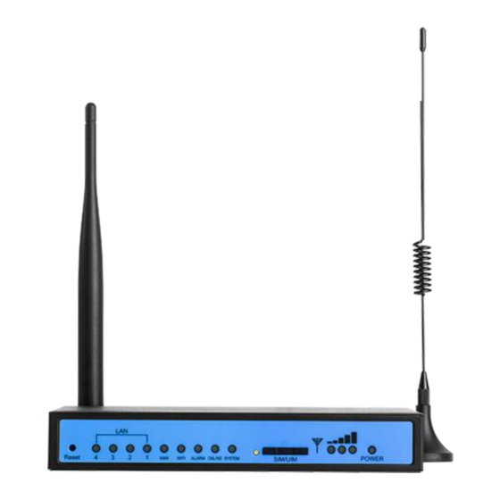
2.3 LED Indicators TR341 Series Router provides 7 LED indicators, as following. Indicator Status Content Power Powered On Powered Off 1 Lights Signal weak Signal 2 Lights Signal Middium Strength 3 Lights Signal Strong System Blink System works perfect System doesn’t work... -
Page 12: Reset
2.4 Reset You can press the Reset button to reset settings to factory defaults to solve the problem of incorrect configuration that makes you couldn’t access to internet, login and management, etc. Use a needle object(such as pen) to insert into hole of ‘Reset’, hold until all the LED indicators turn off. -
Page 13: View
3.1 View View page shows the basic system information including System, Network, Routes, System Log, VPN Status. Checking the following details information. 3.1.1 System System page show you an overview of TR341 information like SN, Firmware version, Memory usage, etc. -
Page 14: Network
3.1.2 Network Network page display the current WAN status, like network type, IP address, Connect Status, and so on. Also indicate the LAN Status, Wireless Status, DHCP Leases. -
Page 15: Routing Tables
3.1.3 Routing Tables Display ARP list and active routing tables. -
Page 16: System Log
3.1.4 System Log System log page continuous print the current running status syslog. It is useful for troubleshooting when there are some features working not as expected. System log page provide three buttons for “Clear Log” which empty current printed log, “Save Log” which saving current printed log as a file, and “Refresh Log”... -
Page 17: Setup
3.2 Setup Setup page includes WAN, LAN, Wireless, Wireless Client, Online Detection, Diagnostics menus, which is for you configuring the features accordingly. 3.2.1 WAN WAN Setting contains General Setup which provide configuration option for setting “Connection Type” and relevant items. It supports “Static IP”, “DHCP”, “PPPoE”, “3G”, “LTE”, “Unmanaged”... - Page 18 Note, 1) PAP/CHAP Username password Only when you are using a private network SIM card, if you’re using public network SIM card, just keep it as null. 2) Choose Dial Number when you are using 3G type, different carriers may have different dial number, please ask your carrier for this info if you have questions.
-
Page 19: Lan
3.2.2 LAN Menu of LAN are mainly for configuring IP address of TR341, set the IP address range of DHCP server, or disable DHCP. 1) Common Configuration IPv4 Address To configure IP address of LAN port. IPv4 Netmask The netmask of LAN port IP address. IPv4 Gateway Specify the next-hop routing gateway. -
Page 20: Wireless
2) DHCP Server Settings Disable DHCP Click to disable DHCP server. Start Assign the IP address of DHCP server. For example, 100 means IP address starts from 192.168.1.100. Limit Assignable number of IP address, to ensure numbers of IP address of start and limit not exceed 250. - Page 21 1) WIFI 2.4G Provide Enable or Disable option for the WIFI function switch. 2) Network Name(SSID) WIFI network name setting. 3) Channel Support 1-13 channels or auto options, default value is auto, channel can be changed automatically. 4) Mode Support 802.11b, 802.11g, 802.11bg, 802.11bgn options. This may related to the maximum speed of WiFi.
-
Page 22: Wireless Client
When Hide SSID enabled, SSID is invisible, and user need to enter the SSID to share the WIFI. Advanced Settings related to some specific parameters setting, this is for professional users, contact Bivocom support team in case you have further questions. 3.2.4 Wireless Client Wireless Client menu provide connecting network from local WiFi Hotspot, this setting... -
Page 23: Online Detection
related to WAN setting when you select Static IP or DHCP connection type. Enable wireless client and apply it, it will list all WiFi hotspots which can be detected. Join one of it, will ask you input the password if hotspot request. 3.2.5 Online Detection Online detection feature checking the network connection status periodically, if there has issue of connection, router will auto reconnect. - Page 24 1) Detection Type There are 3 types: ping, traceroute and DNS. Ping Router will ping an IP address periodically, if works, that means router is online. Traceroute Traceroute will trace routing path, if achieves the target address, that means router is online. ...
-
Page 25: Diagnostics
3.2.6 Diagnostics Diagnostics feature allow user check the network connection status manually. There are 3 types of diagnostics: ping, traceroute and nslookup Parameter of ping and traceroute can be a Domain Name or an IP address, used for checking if router is online or not. While nslookup is to analytic domain. 1) Ping Click ping, then you can check if there is response from an IP address, as bellow. -
Page 26: Port Forwarding
connection available. 3.3.2 Port Forwarding Comparing with DMZ, Port Forwarding is for more precise control, user can forward the data packet of a port to a host of LAN, to forward different port to different host. 1) Name You can name the rule you created. 2) Protocol You can choose TCP, UDP, or TCP/UDP. -
Page 27: Traffic Rules
After configured above-mentioned, click ‘Add’, then a new rule will be added, and click ‘Save & Apply’, to have the rule take effect. There are more setting items when click “Edit” button. 3.3.3 Traffic Rules Traffic rules is used for Firewall setting like opening some ports on router, such as remote access the configuration page of router, you can open port 80. - Page 28 1) Restrict to Address Family You can choose IPv4, IPv6, or Pv4/IPv6. 2) Protocol To choose the protocol you want for access control, it can TCP, UDP or TCP/UDP. 3) Source MAC Address To choose the source MAC address of data packet. 4) Source Address To choose the source IP address of data packet.
-
Page 29: Custom Settings
To choose the source port of data packet. 6) Destination Address To choose the destination IP address of data packet. 7) Destination Port To choose the destination port of data packet. 8) Action If the above-mentioned conditions matched, then you can choose below actions. ... - Page 30 1) PPTP Client 1. PPTP Client You can enable or disable PPTP client. 2. Server Address To enter the IP address or Domain Name of PPTP server. 3. User Name and Password To enter the user name and password provided by server. 4.
-
Page 31: L2Tp
2) PPTP Server 1. PPTP Server You can enable or disable PPTP server. 2. Server Local IP To enter the server local IP address. 3. IP Address Range Type the range of assigned IP address. 4. Enable MPPE Encryption. You can enable MPPE encryption here. 5. - Page 32 1) L2TP Client...
- Page 33 1. L2TP Client You can enable or disable L2TP client. 2. Server Address To enter the IP address or Domain Name of L2TP server. 3. User Name and Password To enter the user name and password provided by server. 4. Remote Subnet To enter the remote subnet, for example, if LAN of L2TP server is 192.168.2.1, then you can enter remote subnet 192.168.2.0.
- Page 34 2) L2TP Server 1. L2TP Server You can enable or disable L2TP server. 2. Server Local IP To enter the server local IP address. 3. IP Address Range Type the range of assigned IP address. 4. Enable MPPE Encryption. You can enable MPPE encryption here. 5.
-
Page 35: Openvpn
3.4.3 OpenVPN 1) OpenVPN... -
Page 36: Ipsec
You can enable or disable OpenVPN. 2) Topology Choose the topology, it can be point to point or subnet Note: For point to point, a tunnel will be established between 2 devices. While for subnet, multi devices will be connected to one server. 3) Role When topology is subnet, you need to choose you want it be a server or client. - Page 37 1) Peer Address To enter peer IP address or Domain Name, if choose as a server, you don’t need to enter 2) Negotiation Method You can choose ‘Main’ or ‘Aggressive’. 3) Tunnel Type You can choose ‘Site to Site, ‘Site to Host’, ‘Host to Host’, ‘Host to Site’. 4) Local Subnet Local subnet and mask, like 192.168.10.0/24.
-
Page 38: Gre
Peer subnet and mask, like 192.168.20.0/24. 6) IKE Encryption Algorithm IKE phase encryption method 7) IKE Lifetime To set up IKE lifttime. 8) Local Identifier Local identifier of channel, can be an IP address or domain name. 9) Peer Identifier Peer identifier of channel, can be an IP address or domain name. -
Page 39: Static Routing
3.5.2 Static Routing Static routing is used to add a routing table entry. Interface: To choose which interface you want to add routing. Target: Can be a host IP, or subnet. IPv4 Netmask: The netmask of subnet, if the target is host, the netmask shall be 255.255.255.255. -
Page 40: Gps Location
3.5.4 GPS Location GPS location will report GPRMV information regularly, saying longitude and latitude information. And this function is used for accurate location of outdoor open area. GPS Source: External for getting GPS data from independent GPS module (Option), while Dongle for getting GPS data from cellular module which may not so accurate. -
Page 41: Dynamic Dns
Server Address: The IP address of server that you want the router to report the location, which is based on TCP connection. Server Port: The port of server. Report Interval: The interval time for auto report of router location, default value is 60 seconds. - Page 42 User Name The username you register at DDNS service provider. User Password The password you set up when registering the user name at DDNS service provider. Host Name The register domain you want to bundle. 3.4.6 SNMP TR341 router provide SNMP feature for manage the device via SNMP.
-
Page 43: Dhcp And Dns
3.5.7 DHCP and DNS TR341 provide DHCP and DNS setting via Dnsmasq package, it support configure DHCP server related settings and DNS forwarding setting if your network request specific parameters. Also support set static Leases. Normally leave it as default. -
Page 44: Data Collect
3.6 Data Collect Data Collect settings is for TR341 acquiring data from slave devices in serial ports, Ethernet ports, with Modbus protocol and other customized protocols. -
Page 45: Basic Setting
3.6.1 Basic Setting Enable or Disable the data collect feature, setting the data acquire and report period and other related options. 1) Data Collect: Enable or Disable data collect feature. 2) Collect Period: Set the period of data acquire from slave devices. 3) Report Period: Set the Period of data report to server. -
Page 46: Modbus Rules Setting
3.6.3 Modbus Rules Setting Modbus Rules Setting is for TR341 as a Modbus master to acquire data from slave devices base on Modbus protocol. You can configure unlimited Modbus rules on it. TR341 provide the options of definable factor name, device ID, function code, register address and count register number, please following the slave device datasheet to get those information. -
Page 47: Server Setting
Click “Edit” button for more details setting, 3.6.4 Server Setting Server setting menu allows user set the data center address with multiple protocols, the standard TR341 support TCP, UDP, HTTP, MQTT, and Modbus TCP. For the data format,... -
Page 48: Administrate
TR341 support different Encapsulation type, include “Transparent”, “Json”, and “HJ212” (special for some Environment SCADA). Also TR341 accept customize specific protocols for your data center. 3.7 Administrate Administrate page provide the administrator level setting for system, like password setting, Timezone setting, Backup and Reset setting, etc. 3.7.1 System System page provide the basic system information setting like Hostname, Timezone, Language, etc. -
Page 49: Password
3.7.2 Password To revise the password of router. 3.7.3 Time Setting System time type includes RTC (Real Time Clock) and NTP (Network Time Protocol). RTC will save time even router is powered off, while for NTP, router will connect to NTP server which requires internet connection, time won’t be saved once powered off. - Page 50 1) Current System Time Display the time of router. 2) System Time Type It includes NTP and RTC mentioned above, and different type has different configuration parameters You can update data and time yourself. RTC Data Format must be: 20xx-xx-xx (Year-Month-Day), or you will fail to update it. RTC Time Format must be xx: xx: xx (Hour-Min-Second), or you will fail to update it.
-
Page 51: Log Settings
Update Interval How long to sync the time with NTP server, default time is 600 seconds. 3.7.4 Log Settings Log settings is for configuring the output parameters of system log. 1) Output to Device You can output the log to serial port, or specified file path, or external storage device, and the default path is:/var/log/ 2) Log Size Set up the size of log, default value is 64KB. -
Page 52: Backup And Reset
3.7.5 Backup and Reset User can either backup the configuration of router as a .gz file, or reset all settings to factory defaults. 1) Download Backup Click to generate a configuration file in format of “backup-router-2016-**-**.tar.gz”. 2) Reset to Default Click ‘Perform Reset’, and a pop-up confirmation box with ‘Really Reset All Changes’... -
Page 53: Remote Management
Click ‘proceed’ to start the firmware upgrade, or click ‘cancel’ to stop the firmware upgrade. 3.7.7 Remote Management Remote Management feature allows TR341 connect with Bivocom Device Management Platform identify by Device Number for remote management, like firmware upgrade, configuration change, etc. - Page 54 Once it registered, on the Bivocom Device management platform, you will see the connection status as “Online” and you can configure it via DMP webUI. 1) Server Address Type the specified login server address you want to remote mange the router, it can be either an IP address or Domain Name.
-
Page 55: Manual Reboot
4) Device Number Define an individual Device ID for router and as identify on DMP. 3.7.8 Manual Reboot Click ‘Perform Reboot’, and a pop-up confirmation box with ‘Really Reboot’ will display, then click ‘OK’ to reboot the router. 3.7.9 Schedule Reboot Schedule reboot feature allow you preset the rules of device reboot, by period interval or by a certain time point.
Need help?
Do you have a question about the TR341 Series and is the answer not in the manual?
Questions and answers