Advertisement
Quick Links
Advertisement

Subscribe to Our Youtube Channel
Related Manuals for Premium levella PRF32405XW


Summary of Contents for Premium levella PRF32405XW
- Page 1 Ser vice Manual (PRF32405XW/ PRF32406XS)...
-
Page 2: Table Of Contents
CONTENTS PARTS IDENTIFICATION ..........................1 REFRIGERATION CIRCUIT ..........................2 CIRCUIT DIAGRAM............................3 SAFETY PRECAUTIONS ..........................4-5 USING INTRODUCTION ..........................6-8 DISASSEMBLY COMMON PARTS OF FREEZER ……………………….……....…………....…………..…9-18 ◆ DOOR REVERSAL INSTRUCTIONS ◆ CARE & MAINTENANCE ◆ Checking the compressor and replacing PTC and Overload protector ◆ Checking the thermostat and replacing thermostat EXPLODED VIEW ............................19 TROUBLESHOOTING.. -
Page 3: Parts Identification
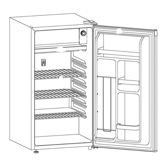
PARTS IDENTIFICATION Page 1 FEATURES 1. Freezer Compartment with Door 2. Thermostat Dial and Push Button Defrost 3. Drip Tray 4. Plastic Coated Shelves 5. Magnetic Gasket: Tight fitting door seal keeps all the cooling power locked inside. 6. CANSTOR: Holds 355ml cans of pop, juice, or beer. 7. -
Page 4: Refrigeration Circuit
REFRIGERATION CIRCUIT Page 2 evaporator Basic refrigeration schematic capillary filter Condenser compressor... -
Page 5: Circuit Diagram
CIRCUIT DIAGRAM Page 3... -
Page 6: Safety Precautions
SAFETY PRECAUTIONS Page 4 SAFETY REQUIREMENTS DANGER: Risk of fire or explosion. Flammable refrigerant used. Do not puncture refrigerant tubing. • Do not use mechanical devices to defrost refrigerator. • Ensure that servicing is done by factory authorized service personnel, to minimize product damage or safety issues. •... - Page 7 SAFETY PRECAUTIONS Page 5 SAFETY REQUIREMENTS This appliance is not intended for use by persons (including children) whose physical, sensory or mental capabilities may be different or reduced, or who lack experience or knowledge, unless such persons receive supervision or training to operate the appliance by a person responsible for their safety.
-
Page 8: Using Introduction
USING INTRODUCTION Page 6 LOCATION • Two people should be used when moving the appliance. • Remove interior and exterior packaging prior to installation. Wipe the outside of the appliance with a soft, dry cloth and the inside with a lukewarm wet cloth. - Page 9 USING INTRODUCTION Page 7 TEMPERATURE SELECTION The temperature of the appliance can be adjusted by turning the thermostat dial. The thicker, darker part of the blue line is the coldest setting. The thinner, lighter part of the blue line is the warmest setting. The “O”...
- Page 10 USING INTRODUCTION Page 8 OUTER DIMENSIONS...
- Page 11 DISASSEMBLY COMMON PARTS OF FREEZER Page 9 DOOR REVERSAL INSTRUCTIONS If the appliance is placed on its back or side for any length of time during this process, it must be allowed to remain upright for 6 hours before plugging it in to avoid damage to the internal components.
- Page 12 DISASSEMBLY COMMON PARTS OF FREEZER Page 10 CARE & MAINTENANCE CLEANING Ensure the appliance is unplugged before cleaning. • To clean the inside of the appliance, use a soft cloth and a solution of a tablespoon of baking soda to one quart of water or a mild soap solution or some mild detergent.
- Page 13 DISASSEMBLY COMMON PARTS OF FREEZER Page 11 CARE & MAINTENANCE POWER FAILURE Most power failures are corrected within a few hours and should not affect the temperature of your appliance if you minimize the number of times the door is opened. If the power is going to be off for a longer period of time, take the proper steps to protect your contents.
- Page 14 DISASSEMBLY COMMON PARTS OF FREEZER Page 12 CARE & MAINTENANCE MOVING • Make sure the appliance is empty. • Secure the shelves with tape. • Secure the door with tape. • Turn the adjustable foot up to the base to avoid damage. •...
- Page 15 DISASSEMBLY COMMON PARTS OF FREEZER Page 13 Checking the compressor After the compressor is powered on separately, the compressor does not start and exhaust. Use a multi-meter to test the resistance between C & M, C&S and S&M : Normal range of C&M : About 8.76~11.85Ω Normal range of C&S : About 7.48~10.12Ω...
- Page 16 DISASSEMBLY COMMON PARTS OF FREEZER Page 14 Checking the compressor accessory Remove the combined PTC starter and overload protector model : ZHB54-120P4.7 A...
- Page 17 DISASSEMBLY COMMON PARTS OF FREEZER Page 15 Checking the compressor accessory Compressor Protector test —— Use a multi-meter to test the resistance between the two terminals as the pic show : If there show 000 or almost 0 then it is OK. If there is no response then it is broken.
-
Page 18: Disassembly Common Parts Of Freezer
DISASSEMBLY COMMON PARTS OF FREEZER Page 16 Checking the compressor accessory Compressor PTC starter test —— Use a multi-meter to test the resistance between the two terminals as the pic show If there show the number is between about 3.7-5.7 then it is OK. If there show 000 or no response then it is broken. - Page 19 DISASSEMBLY COMMON PARTS OF FREEZER Page 17 The instruction of replacing PTC and Overload protector 1.Remove the fastening screws 2.Remove the Compressor Wire Clamp Screw and Compressor Wire Clamp 3.Remove the cover 4.Replace the combined PTC starter and overload protector...
- Page 20 DISASSEMBLY COMMON PARTS OF FREEZER Page 18 Checking the thermostat Use a multi-meter to check the C-L terminal is on or off. The instruction of replacing thermostat thermostat assembly Evaporator door Tapping Screw 4×16 1.Remove the Evaporator door 2.Remove the tapping screw 4×16 3.Remove the thermostat assembly and replace the thermostat...
-
Page 21: Exploded View
EXPLODED DRAWING Page 19... -
Page 22: Troubleshooting
TROUBLESHOOTING Page 20...
Need help?
Do you have a question about the PRF32405XW and is the answer not in the manual?
Questions and answers