Table of Contents
Advertisement
Quick Links
Advertisement
Table of Contents

Subscribe to Our Youtube Channel
Related Manuals for Premium levella PFV1405XW


Summary of Contents for Premium levella PFV1405XW
- Page 1 Ser vice Manual PFV1405XW PFV1406XS...
-
Page 2: Table Of Contents
CONTENTS PARTS IDENTIFICATION ..........................1 REFRIGERATION CIRCUIT .........................2 CIRCUIT DIAGRAM...........................3 SAFETY PRECAUTIONS ..........................4~5 USING INTRODUCTION ..........................6~9 DISASSEMBLY COMMON PARTS OF REFRIGERATOR…………………..…………....…………....…………..10~20 ◆ CARE & MAINTENANCE ◆ Checking the compressor and replacing PTC and Overload protector ◆ Compressor Capacitor install and removal EXPLODED DRAWING ..........................21 TROUBLESHOOTING..........................22... -
Page 3: Parts Identification
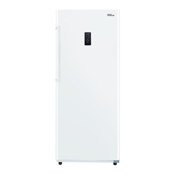
PARTS IDENTIFICATION Page 1 1.Door 2.Upper air duct plate 3.Glass shelf I 4.Lower air duct board 5.Glass shelf II 6.Lower drawer 7.Adjustable Feet 8.Door shelf... -
Page 4: Refrigeration Circuit
REFRIGERATION CIRCUIT Page 2 Basic refrigeration schematic... -
Page 5: Circuit Diagram
CIRCUIT DIAGRAM Page 3... -
Page 6: Safety Precautions
SAFETY PRECAUTIONS Page 4 AFETY REQUIREMENTS DANGER: Risk of fire or explosion. Flammable refrigerant used. Do not puncture refrigerant tubing. • Do not use mechanical devices to defrost refrigerator. • Ensure that servicing is done by factory authorized service personnel, to minimize product damage or safety issues. •... - Page 7 SAFETY PRECAUTIONS Page 5 SAFETY REQUIREMENTS This appliance is not intended for use by persons (including children) whose physical, sensory or mental capabilities may be different or reduced,or who lack experience or knowledge, unless such persons receive supervision or training to operate the appliance by a person responsible for their safety.
-
Page 8: Using Introduction
USING INTRODUCTION Page 6 LOCATION • Two people should be used when moving the appliance. • Remove interior and exterior packaging prior to installation. Wipe the outside of the appliance with a soft, dry cloth and the inside with a lukewarm wet cloth. - Page 9 USING INTRODUCTION Page 7 TEMPERATURE SETTING CONTROL PANEL When the temperature display is display will extinguish automatically after three minutes. When the display is extinguishing, press the keys to activate it, then key function will start work. Below operating instruction only applies to the display is unlocked •...
- Page 10 USING INTRODUCTION Page 8 OPEN DOOR ALARM This appliance is equipped with a door alarm that will sound if the door is left open for more than 3minutes. The alarm will beep and the display will flash continuously until the door is closed. HANDLE INSTALLATION The appliance ships with the handle inside the cabinet to protect it from damage.
- Page 11 USING INTRODUCTION Page 9 OUTER DIMENSIONS W710...
- Page 12 DISASSEMBLY COMMON PARTS OF REFRIGERATOR Page 10 CARE & MAINTENANCE CLEANING Ensure the appliance is unplugged before cleaning. • To clean the inside of the appliance, use a soft cloth and a solution of a tablespoon of baking soda to one quart of water or a mild soapsolution or some mild detergent.
- Page 13 DISASSEMBLY COMMON PARTS OF REFRIGERATOR Page 11 CARE & MAINTENANCE POWER FAILURE Most power failures are corrected within a few hours and should not affect the temperature of your appliance if you minimize the number of times the door is opened. If the power is going to be off for a longer period of time, take the proper steps to protect your contents.
- Page 14 DISASSEMBLY COMMON PARTS OF REFRIGERATOR Page 12 CARE & MAINTENANCE ENERGY SAVING TIP The appliance should be located in the coolest area of the room, away from heat producing appliances, and out of direct sunlight. Do not overload the unit or block any ventilation openings. MOVING •...
- Page 15 DISASSEMBLY COMMON PARTS OF REFRIGERATOR Page 13 CARE & MAINTENANCE ERROR CODES • E1: The freezer sensor failure • E2: Freezer defrosting sensor failure • E3: The freezer sensor failure and freezer defrosting sensor failure • C0: Communication failure • dr: Door opening alarm •...
-
Page 16: Disassembly Common Parts Of Refrigerator
DISASSEMBLY COMMON PARTS OF REFRIGERATOR Page 14 CARE & MAINTENANCE stainless screw Lower Air Duct Plate screw Temperature control probe cover Sensor Defrosting sensor 1.Remove the stainless screw 2.Remove the temperature control probe cover 3.Remove theSensor and replace the Sensor 1.Remove the Lower Air Duct Plate screw 2.Remove theDefrosting sensor and replace the Defrosting sensor... - Page 17 DISASSEMBLY COMMON PARTS OF REFRIGERATOR Page 15 Checking the compressor Resistance range at 25℃: Resistance between C and M 5.67~6.93Ω(6.3Ω±10%); Resistance between C and S 6.03~7.37Ω(6.70Ω±10%); Resistance between S and M 11.70~14.30Ω(13.00Ω±10%)
- Page 18 DISASSEMBLY COMMON PARTS OF REFRIGERATOR Page 16 Checking the compressor accessory Disassemble the PTC starter and Over loaded Protector 1.Remove the PTC and OLP components separately 2.Use a flat-head screwdriver against the hook of the OLP, then press it down 3.When the clip is unhooked, the PTC and OLP can be separated...
- Page 19 DISASSEMBLY COMMON PARTS OF REFRIGERATOR Page 17 Checking the compressor accessory Compressor Protector test —— Use a multi-meter to test the resistance between the two end as the pic show : If there show 000 or almost 0 then it is OK. If there is no response then it is broken.
- Page 20 DISASSEMBLY COMMON PARTS OF REFRIGERATOR Page 18 Checking the compressor accessory Compressor PTC starter test —— Use a multi-meter to test the resistance between the two end as the pic show If there show the number is between about 3.5-5.8 then it is OK. If there show 000 or no response then it is broken.
- Page 21 DISASSEMBLY COMMON PARTS OF REFRIGERATOR Page 19 The instruction of replacing PTC and Overload protector 1.Remove the fastening screws 2.Remove the Compressor Wire Clamp Screw and Compressor Wire Clamp 3.Remove the cover 4.Replace the PTC Starter & OLP...
-
Page 22: Compressor Capacitor Install And Removal
DISASSEMBLY COMMON PARTS OF REFRIGERATOR Page 20 Compressor Capacitor install and removal Install Capacitor: 1.M-type clip is aligned with the rectangular hole on the compressor baseplate 2.Press down hard till hear a “ding” 3.Check whether the capacitor is fastened or not Remove Capacitor:... -
Page 23: Exploded Drawing
EXPLODED DRAWING Page 21 Display panel Flow plate Drainage elbow Display plate Cap nail Self tapping screw(4x12) According to the face Hinge gasket Drain connection pipe 819 Stainless steel(5x16) Hinge base Exhaust cover White side door handle Padded machine tapping Exhaust cover plates Hydrodynamic M8 Nut... -
Page 24: Troubleshooting
TROUBLESHOOTING Page 22...
Need help?
Do you have a question about the PFV1405XW and is the answer not in the manual?
Questions and answers