Table of Contents
Advertisement
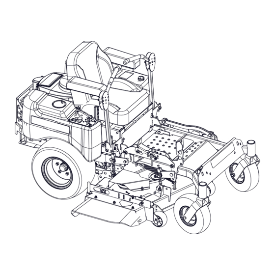
Max Zoom
Owner/Operator Manual
Manuel du Propriétaire/Utilisateur
E10
The use of any gasoline exceeding 10% ethanol (E10) or
10% MTBE will void the product warranty.
L'utilisation d'une essence contenant plus de 10%
d'éthanol (E10) ou de 10% de MTBE annulent la garantie.
ENGLISH
FRANÇAIS
™
Models
991085 – Max Zoom 48
(SN 050000 +)
991086 – Max Zoom 52
(SN 050000 +)
991087 – Max Zoom 60
(SN 050000 +)
991118 – Max Zoom 48 CARB
(SN 000101 +)
•
04829800A
3/15
Printed in USA
Advertisement
Table of Contents

Related Manuals for Ariens Max Zoom 48 CARB


Summary of Contents for Ariens Max Zoom 48 CARB
- Page 1 991086 – Max Zoom 52 (SN 050000 +) 991087 – Max Zoom 60 (SN 050000 +) 991118 – Max Zoom 48 CARB (SN 000101 +) The use of any gasoline exceeding 10% ethanol (E10) or 10% MTBE will void the product warranty.
-
Page 2: Table Of Contents
TABLE OF CONTENTS SAFETY......4 STORAGE ..... . . 31 ASSEMBLY . - Page 3 PRODUCT REGISTRATION drive position or PTO is engaged (On). See Safety Interlock System on The Ariens dealer must register the product page 14. at the time of purchase. Registering the 3. Fill out Original Purchaser Registration product will help the company process Card and return the card to Ariens.
-
Page 4: Safety
SAFETY SIGNAL WORDS WARNING: This cutting machine is The safety alert symbols above and signal capable of amputating hands and words below are used on decals and in this feet and throwing objects. Failure to manual. observe the safety instructions in the manuals and on decals could Read and understand all safety messages. - Page 5 Safety Decal Identification 07800403 07800401 KEEP HANDS and FEET AWAY Figure 2 Safety Decal Description 1. DANGER! Keep hands away from all rotating or moving parts. DANGER! Keep all guards and shields in place. Read and understand the operator’s manual before 1.2 Discharge Hazard operating unit.
- Page 6 1.5 Bystander Hazard Do not operate mower unless all guards are in operating position or bagger DO NOT operate the unit in is attached. the presence of bystanders. 1.3 Tipping Hazard Avoid tipping hazard. Do not carry passengers. Look behind when operating DO NOT operate on slopes over 15°.
- Page 7 3. DANGER! 5. HOT SURFACES! Discharge Hazard – NEVER direct discharge toward DO NOT touch parts people, pets or property. which are hot from Thrown objects can cause operation. ALWAYS allow injury or damage. parts to cool. Amputation Hazard – NEVER stick hands or feet 6.
- Page 8 Improper use of power equipment can cause Use extreme care when approaching blind serous permanent injury or death to the corners, shrubs, trees, or other objects that operator or a bystander. may block your view of a child. Understand: Keep children out of the mowing area and in the watchful care of a responsible adult •...
- Page 9 Do not mow in reverse unless absolutely Operation necessary. Always look down and behind Be sure the area is clear of bystanders before and while backing. before operating. Stop machine if anyone Stop engine before removing grass catcher enters the area. or unclogging chute.
- Page 10 Watch for holes, ruts, bumps, rocks, or other Use only an approved gasoline container. hidden objects. Uneven terrain could Never store the machine or fuel container overturn the machine. Tall grass can hide where there is an open flame, spark, or pilot obstacles.
- Page 11 Lower cutting deck unless a positive when necessary. mechanical lock is used. Use only Ariens Company-recommended Allow engine to cool before servicing. attachments that are appropriate to your use Moving parts can cut or amputate fingers or and can be used safely in your application.
-
Page 12: Assembly
ASSEMBLY 8. Fill Engine Fuel Tank – Fill fuel tank. DO WARNING: AVOID INJURY. Read NOT OVERFILL! See Filling Fuel Tank and understand entire Safety section on page 16. before proceeding. NOTE: See engine manual for fuel type. Package Contents 9. -
Page 13: Controls And Features
CONTROLS AND FEATURES 3, 9 Figure 3 1. Fuel Tank and Cap 2. Steering Levers 3. Hydraulic Oil Reservoir (under seat) 4. Ignition Switch 5. Hour Meter 6. Throttle Lever 7. Choke Control 8. Power Take Off (PTO) Switch 9. Battery (under seat) 10. -
Page 14: Operation
C. To turn left, pull the left back or push your Ariens dealer for repairs. the right steering control lever forward NOTE: When the parking brake is engaged, or a combination of both. - Page 15 Choke Control Mower Lift Pedal Push the choke lever forward to start a cold engine. Pull the choke lever to the rear when the engine gets warm. OF1680 Throttle Lever Mower lift pedal raises and lowers mower The throttle lever changes deck for mowing or transport.
- Page 16 Operation To add fuel to the fuel tank Press and release the 1. Clean fuel caps and surrounding area to toggle button (2) to prevent dust, dirt, and debris from shift between different entering fuel tanks. functions. 2. Remove fuel caps. Press and hold the IMPORTANT: Refer to Engine Manual for toggle button to reset...
- Page 17 IMPORTANT: Excessively oxygenated or STOPPING IN AN EMERGENCY reformulated fuels (fuels blended with alcohols or ethers) can damage the fuel WARNING: Operating unit on slopes may lead to loss of steering system or cause performance problems. If control. When operating on slopes any undesirable operating problems occur, be prepared to react to an use a gasoline with a lower percentage of...
- Page 18 WARNING: Move the steering control levers slowly and keep the throttle control lever at slow speed until you learn how to operate the unit. 3. Bring the steering levers to neutral. 4. Slow the engine down to about 3/4 speed. 5.
-
Page 19: Maintenance Schedule
MAINTENANCE SCHEDULE Proper maintenance can prolong the life of WARNING: AVOID INJURY. Read unit. The following charts show the and understand entire Safety recommended service schedule. More section before proceeding. frequent service may be required due to working conditions (heavy loads, high ambient temperatures, dusty conditions, or airborne debris). -
Page 20: Service And Adjustments
Should engine service be when rotating it into service position. required, it can be obtained from a Ariens Dealer or the engine manufacturer’s 5. When service is complete, lower seat authorized service center. - Page 21 HYDRAULIC FLUID Change Hydraulic Fluid and Filter NOTE: Change hydraulic fluid and filter after WARNING: HYDRAULIC FLUID can the first 75 hours of operation and then every result in severe burns. Fluid in 400 hours. Use 15W-50 synthetic motor oil hydraulic system can penetrate skin (p/n 00057100) or equivalent.
- Page 22 Purging the Hydraulic System WARNING: This adjustment requires operating the engine. Use extreme care to avoid contact with moving parts and hot surfaces. Be sure rear of unit is well supported and secure before starting engine. 1. With the unit up to and facing a wall, jack up the unit so that both drive wheels are off the ground.
- Page 23 Install Factory Battery DO NOT sharpen to this pattern. 1. Replace battery and secure with battery hold down. See Figure 10. DISCARD if more than 1/2 in. (1.27 cm) Sharpen to this pattern. Figure 10 1. Cutting Edge 2. Square Corner 2.
- Page 24 5. Replace battery. See Install Factory Battery or Install U1 Battery on page 23. Jump-Starting Ariens does not recommend jump-starting your unit. Jump-starting can damage engine and electrical system components. See your engine manual for more detailed information.
- Page 25 4. Start the engine, run engine at full 4. Loosen tie rod jam nuts and turn tie rod throttle, and release the parking brake. until steering levers are aligned. 5. Move the steering levers from Forward 5. Tighten jam nut on tie rod, tighten brake to Reverse several times to make sure interlock.
- Page 26 1. Shut OFF engine. Engage parking brake. Remove the ignition key. 2. Remove the spacer, handle, and eccentric spacer from the steering lever. NOTE: Position the right and left handles at the same height position. 3. Install the spacer, handle, and eccentric spacer in the appropriate height position.
- Page 27 1. Footboard in open position 2. Support Frame 1. Parking Brake Cable 3. Pivot 2. Adjuster Figure 19 3. Nuts Figure 18 Replacing Mower Belts NOTE: Long mower belt must be removed to PTO BELT remove short mower belt. WARNING: MOVING PARTS can CAUTION: Use care when releasing cut or amputate body parts.
- Page 28 CAUTION: Use care when releasing idler spring tension. Keep body parts well away from idlers when performing this operation. 3. Slowly release the tension on the hydro pump belt idler until all the tension is removed from the springs. 4. Remove old hydro pump belt from right hand hydrostat sheave first (Figure 22).
- Page 29 MOWER DECKS IMPORTANT: The mower lift arms are not locked unless the cutting height adjustment Anti-scalp Roller Adjustment pin passes all the way through both the deck The anti-scalp rollers are set at the factory for lift cover and shaft. typical mowing height, but can be adjusted for NOTE: Support the mower deck on blocks or high or low cutting conditions (Figure 23).
- Page 30 Leveling the Mower Deck Blade Side-to-Side Level These adjustments should be made on a level surface with the tires inflated to the correct air pressure. Check Blade Level and Pitch 1. Raise mower deck to a 3" (7.62 cm) cutting height. 2.
-
Page 31: Storage
CLUTCH ADJUSTMENT STORAGE If clutch fails to engage or disengage properly or begins to make abnormal noise, check the WARNING: AVOID INJURY. Read air gap adjustment at the three inspection and understand entire Safety slots. section before proceeding. To check: 1. -
Page 32: Accessories
Bagger Adapter Kit 48" Decks 07200026 PTO Belt – 52" Decks 89100300 HD Series Bagger 07200028 PTO Belt – 60" Decks 71508900 Hub Cap Set (2) Ariens 10" 07211500 Traction (Hydro Pump) Belt 79102300 Kit, Universal Flextend 00450200 Blade – 48" Decks... -
Page 33: Specifications
SPECIFICATIONS Model Number 991085 991086 991087 991118 Model Max Zoom Max Zoom Max Zoom Max Zoom 48 CARB Engine Kohler 7000 Kohler 7000 Kohler 7000 44.2 (724.3) Engine Displacement – in (cc) Governed RPM (May be different 3,600 ± 75 from maximum RPM) Liquid or Air Cooled Speed... -
Page 34: Warranty
Register the product immediately at the time of sale. If the dealer does not register the product, the customer must complete the product registration card in the literature package and return it to the Ariens Company, or register the unit online at www.ariens.com, www.gravely.com, www.countax.com. - Page 35 Exclusions – Items Not Covered by This Warranty • Parts that are not genuine Ariens, Gravely or Countax service parts are not covered by this warranty and may void the warranty. • Damages resulting from the installation or use of any part, accessory, or attachment which is not approved by the Ariens Company for use with product(s) identified herein are not covered by this war- ranty.
- Page 36 655 West Ryan Street Brillion, WI 54110 920-756-4688 Fax 920-756-2407 www.ariens.com www.ariens.com.au WARNING The engine exhaust from this product contains chemicals known to the State of California to cause cancer, birth defects or other reproductive harm.
Need help?
Do you have a question about the Max Zoom 48 CARB and is the answer not in the manual?
Questions and answers