Sign In
Upload
Download
Table of Contents
Contents
Add to my manuals
Delete from my manuals
Share
URL of this page:
HTML Link:
Bookmark this page
Add
Manual will be automatically added to "My Manuals"
Print this page
×
Bookmark added
×
Added to my manuals
Manuals
Brands
LG Manuals
Microwave Oven
MC-784DC
Service manual
LG MC-784DC Service Manual
Microwave/grill/ convection oven
Hide thumbs
1
2
Table Of Contents
3
4
5
6
7
8
9
10
11
12
13
14
15
16
17
18
19
20
21
22
23
24
25
26
27
28
29
30
31
32
33
34
35
page
of
35
Go
/
35
Contents
Table of Contents
Bookmarks
Table of Contents
Safety Precautions
Table of Contents
Specifications
Cautions
Installations
Operating Instructions
Features
Control Panel
Operating Sequence
Schematic Diagram
Circuit Description
Service Information
Tools and Measuring Instruments
Microwave Leakage Test
Measurement of Microwave Power Output
Disassembly and Adjustment
Interlock Continuity Test
Component Test Procedure
Trouble Shooting Guide
Advertisement
Quick Links
Download this manual
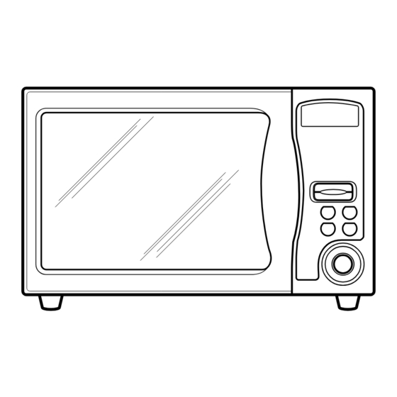
MICROWAVE/GRILL/
CONVECTION OVEN
SERVICE MANUAL
MODEL : MC-784DC/MC-785DC/MC-785BC
CAUTION
BEFORE SERVICING THE UNIT, READ THE SAFETY PRECAUTIONS
IN THIS MANUAL.
Table of
Contents
Previous
Page
Next
Page
1
2
3
4
5
Advertisement
Table of Contents
Need help?
Do you have a question about the MC-784DC and is the answer not in the manual?
Ask a question
Questions and answers
Related Manuals for LG MC-784DC
Microwave Oven LG MC7849HS Owner's Manual
Microwave/grill/convection oven (38 pages)
Microwave Oven LG MC7889DR Owner's Manual
(41 pages)
Microwave Oven LG MC-7880SL Owner's Manual
(37 pages)
Microwave Oven LG MC7889D Owner's Manual
(37 pages)
Microwave Oven LG MC-7884NLC Owner's Manual
Microwave/grill/convection oven (50 pages)
Microwave Oven LG MC-7644A Owner's Manual
Microwave/grill/ convection oven (34 pages)
Microwave Oven LG MC7887AS Owner's Manual
(37 pages)
Microwave Oven LG MC7887AB Owner's Manual
(34 pages)
Microwave Oven LG MC-7844NLC Owner's Manual
Microwave/grill/convection oven (52 pages)
Microwave Oven LG MC-7847B Owner's Manual
(36 pages)
Microwave Oven LG MC7887A Owner's Manual
(101 pages)
Microwave Oven LG MC-785BC Service Manual
Microwave/grill/ convection oven (35 pages)
Microwave Oven LG MC-7884NLCR Owner's Manual
Microwave/grill/convection oven (57 pages)
Microwave Oven LG MC7642E Owner's Manual
Microwave/grill/convection oven (36 pages)
Microwave Oven LG MC-766YS Service Manual
(36 pages)
Microwave Oven LG MC-7683D Service Manual
(35 pages)
This manual is also suitable for:
Mc-785dc
Mc-785bc
Table of Contents
Print
Rename the bookmark
Delete bookmark?
Delete from my manuals?
Login
Sign In
OR
Sign in with Facebook
Sign in with Google
Upload manual
Upload from disk
Upload from URL


Need help?
Do you have a question about the MC-784DC and is the answer not in the manual?
Questions and answers