
Related Manuals for Weldmatic W64


Summary of Contents for Weldmatic W64
- Page 1 ® Weldmatic W64 4RD Wirefeeder Operators Manual Weldmatic Four Roll Drive Enclosed Wirefeeder Model No. W64-0, Iss A 02/12 W64-40 Rev E...
- Page 2 Welding Industries of Australia An ITW Company Telephone: 1300 300 884 Facsimile: 1300 301 884 Email: Info@welding.com.au www.welding.com.au...
-
Page 3: Table Of Contents
Basic Welding Information General Maintenance External Trouble Shooting Wirefeeder Circuit Diagrams Assembly and Parts Lists 10.1 Wirefeeder 10.2 Wirefeed Assembly 10.3 Gun and Cable Assembly 15 10.4 Work Lead & Interconnecting Lead Kit Warranty information Model No W64-0, Iss A 02/12... - Page 4 Recommended shade filter lens Handle on Wirefeeder Pulsed Please note that the handle fitted to Amps MMAW the Weldmatic W64 wirefeeder is 0-100 12-13 intended for carrying the equipment by hand only. 100-150 12-13 150-200 10-11...
- Page 5 Walls, Metals coated with or containing materials ceilings, and floor near work should be that emit fumes should not be heated unless protected by heat-resistant covers or shields. Model No W64-0, Iss A 02/12...
- Page 6 Operators Manual Walls touching combustibles on opposite Hollow castings or containers must be vented sides should not be welded on or cut. Walls, before welding or cutting. They can explode. ceilings, and floor near work should be Never weld or cut where the air may contain protected by heat-resistant covers or shields.
-
Page 7: Introduction
• (This) Operating Manual W64-40. generated by the wire core. If the W64-0, 4RD Wirefeeder is included in a The process is very versatile in that by package with a Weldmatic MIG welder, it will selection of the correct wire composition, also contain the following;... -
Page 8: Specifications
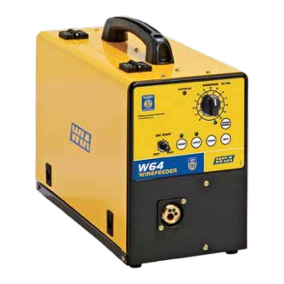
Operators Manual 3 Specifications 4 Controls 1 Power on Indicator Wirefeeder This indicator is illuminated when wirefeeder Supply Voltage is connected to a power source and the power source is switched on. 32 volts AC, (from welding power source) 2 Arc start Rated Supply Current This control can be set to modify arc starting 5 Amps... - Page 9 This can help to reduce operator fatigue during long welding runs. Model No W64-0, Iss A 02/12...
-
Page 10: Wirefeeder Controls
Operators Manual Wirefeeder Controls on Inside Panel Pre Gas Control Sets the time period of gas flow from gun switch on until welding commences, and can be set for 0 – 2 seconds. Post Gas Control This sets the time period of gas flow after welding ceases, and can be set for 0 –... -
Page 11: Installation
Hex electrical contact, and to prevent gas leaks. head bolt inside the hub. The Weldmatic W64 4RD wirefeeder is Feeding the Consumable Wire supplied fitted with WF027 bottom rollers which are suitable for both 0.9mm and At the wirefeeder, release the compression 1.2mm diameter steel wire. -
Page 12: Basic Welding Information
Operators Manual 6 Basic Welding Information Refer to the Weldmatic power source 3 Welding tip is free of obstructions such Operators Manual for gas and weld setting as spatter build-up. Ream out the tip and gun position information. bore with a suitable size oxy-tip cleaner. -
Page 13: Wirefeeder Circuit Diagrams
Weldmatic W64 4RD Wirefeeder 9 Wirefeeder Circuit Diagram Fig 4 Wirefeeder Circuit Diagram Model No W64-0, Iss A 02/12... -
Page 14: Wirefeed Assembly
Operators Manual 10.1 Assembly and Parts List - W64-0 Wirefeeder Fig 5 W64-0 Wirefeeder Assembly Quality Reliability Performance • •... - Page 15 WF042 Four Roll Drive and Euro Adaptor Assembly (see page 14) M0043 Rubber Foot E0041 Gas Valve 24 vdc M0046 Spool Retaining Nut M0044 Spool Holder Assembly (incl nut) Not shown AM343 Current Sensor Model No W64-0, Iss A 02/12...
- Page 16 Operators Manual 10.2 Assembly and Parts List - WF042 Wirefeed Assembly Fig 6 Wirefeed Assembly Item # Part # Description WF045 Roller Retaining Screw Feed rolls WF027 0.9 + 1.2 mm, Solid Wire (fitted) WF026 0.6 + 0.8 mm, Solid Wire WF028 1.2 + 1.6 mm, Solid Wire WF029...
- Page 17 Weldmatic W64 4RD Wirefeeder 10.3 Assembly and Parts List - Gun and Cable Assembly Fig 7 350 Amp Gun and Cable Assembly supplied with Weldmatic 356 and 396 400 Amp Gun and Cable Assembly supplied with Weldmatic Fabricator Item #...
- Page 18 Operators Manual Nozzles To replace liner: Disconnect gun/cable assembly at the Euro adaptor. Remove nozzle (1), gas diffuser (3) and insulator (4). Part # Description Withdraw old liner from the wirefeeder end. BEN-3400C Nozzle, copper, 3/4” I.D , flush Insert new liner and refit gun/cable assembly BEN-3414B Nozzle, brass, 3/4”...
-
Page 19: Work Lead
Weldmatic W64 4RD Wirefeeder 10.4 Assembly and Parts List - Work Lead & Interconnecting Lead Kit (270 & 356) Fig 9 Work Lead & Interconnecting Lead Kit supplied with Weldmatic 356 Item # Part # Description AM311-2/10 Work Lead Includes 1.1... - Page 20 Operators Manual 10.4 Assembly and Parts List - Work Lead & Interconnecting Lead Kit (396 & Fabricator) Fig 10 Work Lead & Interconnecting Lead Kit supplied with Weldmatic 396 & Fabricator Item # Part # Description Work Lead Includes 1.1...
-
Page 21: Warranty Information
This warranty covers the Weldmatic power South Australia, 5039 source and wirefeeder only, and does not extend to the regulator, gun assembly or Ph: 1300 300 884 accessories included in the original purchase Email: info@welding.com.au package. Web: www.welding.com.au Model No W64-0, Iss A 02/12... - Page 22 Operators Manual Notes Quality Reliability Performance • •...
- Page 23 Weldmatic W64 4RD Wirefeeder Notes Model No W64-0, Iss A 02/12...
Need help?
Do you have a question about the W64 and is the answer not in the manual?
Questions and answers