Table of Contents
Advertisement
Quick Links
Weldmatic 215
[internal wirefeeder]
Operators Manual
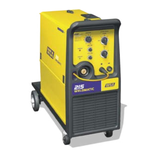
Weldmatic 215 MIG welder
Model No. CP111-0, Iss A
02/05
WELDING INDUSTRIES OF AUSTRALIA
a division of Welding Industries Ltd
ABN 18 004 547 111
Telephone 1300 300 884
Facsimile 1300 301 884
Email: Info@welding.com.au
www.welding.com.au
CP111-40 Rev D
Advertisement
Table of Contents

Related Manuals for Weldmatic 215


Summary of Contents for Weldmatic 215
- Page 1 Weldmatic 215 [internal wirefeeder] Operators Manual Weldmatic 215 MIG welder Model No. CP111-0, Iss A 02/05 WELDING INDUSTRIES OF AUSTRALIA a division of Welding Industries Ltd ABN 18 004 547 111 Telephone 1300 300 884 Facsimile 1300 301 884 Email: Info@welding.com.au www.welding.com.au...
-
Page 2: Table Of Contents
Weldmatic 215 Operators Manual Contents Section General Information Page Safe Practices Introduction Receiving Specifications Controls Installation Normal Welding Sequence Basic Welding Information General Maintenance Trouble Shooting Service Information Assembly and Parts Lists 11.1 Power Source 11.2 Wirefeed assembly 11.3 Gun and Cable Assembly 19 11.4 Work Lead Kit... -
Page 3: Safe Practices
Operators Manual Weldmatic 215 Safe Practices When Using Welding Read First Equipment The information contained in this These notes are provided in the interests manual is set out to enable you to of improving operator safety. They should properly maintain your new equipment... - Page 4 Weldmatic 215 Operators Manual Flammable hair preparations should not be and floor near work should be protected by used by persons intending to weld or cut. heat-resistant covers or shields. A person acting as Fire Watcher must be Toxic Fumes standing by with suitable fire extinguishing...
-
Page 5: Introduction
The Weldmatic 215 has been designed to be used with consumable wires in the range from 0.6mm to 1.2mm diameter. The smaller wire sizes are used when welding at lower currents, such as sheet-metal applications. -
Page 6: Specifications
Maximum Primary Current 42 Amps Recommended Generator kVA 10.1 kVA Rated Output @ 40 Duty cycle based on 10min cycle time 215 Amp, 24.8 V, 15% duty 90 Amp, 18.5 V, 100% duty Welding Current 40-215 Amps Open Circuit Voltage 20-45 V... -
Page 7: Controls
Operators Manual Weldmatic 215 4 Controls Fig 1 Power Source Controls Fig 1 Power Source Controls 1 Wire Speed Control 5 Interval Control This control provides adjustment of the When operating in Cycle Arc mode this control wirefeed speed. Rotating the dial in a clockwise sets the period between welds. -
Page 8: Installation
The effective primary current for the Weldmatic 215 is 16 Amps. The minimum recommended mains circuit breaker rating for a Weldmatic 215 is 20 Amps. Note : Due to normal variations of sensitivity, the tripping time of some 20A circuit breakers... - Page 9 Operators Manual Weldmatic 215 Fitting the gas cylinder Feeding the Consumable Wire Place the gas cylinder on the tray at the rear of At the wirefeed assembly, release the the welder. Retain the cylinder with the chain compression screw and rotate the top roller provided.
-
Page 10: Normal Welding Sequence
The gas valve is energised and gas flow available. commences; The recommended shielding gases for use with • The power source contactor function the Weldmatic 215 are: is initiated. Welding voltage is applied between the work piece and the • Mild Steel Argon + consumable wire. - Page 11 Operators Manual Weldmatic 215 If the voltage is too low the wire will stub and Gun Position stutter, and there will not be a steady arc. If For “down hand” fillet welding, the gun is the voltage is too high the arc will be long with...
-
Page 12: General Maintenance
Weldmatic 215 Operators Manual 8 General Maintenance 7 Welding wire is straight and free of buckles or ‘waviness’. To check, remove 2 or 3 metres of wire from the spool. Clamp one end in a vice or similar, then holding the Before removing the power source or other end pull the wire out straight. -
Page 13: Trouble Shooting
2 Shielding gas is correct for the consumable 1 Power source has overheated. wire in use (refer page 10) The Weldmatic 215 welding power source 3 Welding circuit is making good electrical incorporates an in-built over-temperature connection. Ensure that the work clamp is... -
Page 14: Service Information
Weldmatic 215 Operators Manual 10 Service Information. • SCR module ON / OFF control, phase CAUTION: Mains voltage is present on this selected to minimise transformer inrush control board whenever the power source current is energised. • SCR module protection by output short circuit detection. -
Page 15: Power Source
Operators Manual Weldmatic 215 10-1 Circuit Diagrams - Power Source Fig 8 Power Source Circuit Diagram Quality, Reliability, Performance Model No. CP111-0, Iss A 02/05... - Page 16 Weldmatic 215 Operators Manual 11.1 Assembly and Parts List - Weldmatic 215 Power Source 7 27 7 29 7 30 Fig 9 Weldmatic 215 Power Source Assembly Quality, Reliability, Performance Model No. CP111-0, Iss A 02/05...
-
Page 17: Wirefeed Assembly
Operators Manual Weldmatic 215 Item # Part # Description CP42-24/6 Wheel, Rubber, Castor PAN001 Base CP42-0/3 Wheel, Rubber, Fixed MC11-53/6 Ratchet Cap PAN006 Side Panel, Lower PAN003 Front Panel W29-1/20 Slam Action Catch M0010 Control Knob, Small MC100-54 Control Knob, Large... - Page 18 Weldmatic 215 Operators Manual 11.2 Assembly and Parts List - Wirefeed Fig 10 Wirefeed Assembly Item # Part # Description WF005 Wirefeed Motor WF006 Feedplate WF007 Euro Adapter WF001-5 Compression Screw WF001-4 Top Roller Arm W26-0/13 Inlet Guide W27-0/9 Retaining Screw...
-
Page 19: Gun And Cable Assembly
Operators Manual Weldmatic 215 11.3 Assembly and Parts List - Gun and Cable Assembly Fig 11 BEQ1510AO7CE (180 amp) Gun and Cable Assembly To replace liner: Disconnect gun/cable assembly Item # Part # Description at the Euro adaptor. Remove nozzle (1) and... - Page 20 Weldmatic 215 Operators Manual 11.4 Assembly and Parts List - Work Lead Kit Fig 12 Interconnecting Lead Kit Item # Part # Description Work Lead Includes 1.1 CABW25 Welding Cable 25mm WGEC3 Plug WGEC2 Work Clamp Quality, Reliability, Performance Model No. CP111-0, Iss A 02/05...
-
Page 21: Warranty Information
PERFORMANCE, AND ANY REMEDY FOR BREACH OF CONTRACT TORT OR ANY OTHER Parts and workmanship on Weldarc and Weldmatic equipment are covered for a period LEGAL THEORY WHICH, BUT FOR THIS of 3 years (except for gas regulator, gun cable PROVISION, MIGHT ARISE BY IMPLICATION, and consumables listed below.)
Need help?
Do you have a question about the 215 and is the answer not in the manual?
Questions and answers