
Related Manuals for Axminster Trade AT150SP


Summary of Contents for Axminster Trade AT150SP
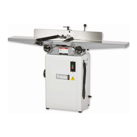
- Page 1 AT150SP Code 104349 AT150SSP Code 106240 Original Instructions AT150SP, AT150SSP 150mm Surface Planers AT: 18/09/2020 BOOK REF: 104709 BOOK VERSION: 05...
-
Page 2: Eu Declaration Of Conformity
EN 859: 2007+ A2: 2012 EN 60204-1: 2006+A1: 2009+AC: 2010 Surface Planer Type AT150SP, AT150SSP Model and conforms to the machinery example for which the EC Type-Examination Certificate No 0Q170113.WFA0U23 has been issued by ECM Ente Certificazione Macchine Srl Signed at: Via Ca’... -
Page 3: What's Included
What’s Included Quantity Item Part Model Number AT150SP, AT150SSP Box 1 150mm Planer Fence and Threaded Clamping Handle Cast Iron Fence Mount & two Hex Bolts/Washers Cutterblock Guard (Aluminium) Cutterblock Guard Arm Table Control Wheels Belt Guard with four Screws and Washers... - Page 4 What’s Included...
- Page 5 What’s Included...
-
Page 6: General Instructions For 230V Machines
General Instructions for 230V Machines • Carry out a final check e.g. check the cutting tool The following will enable you to observe good working practices, keep yourself and fellow workers safe and maintain is securely tightened in the machine and the correct your tools and equipment in good working order. -
Page 7: Specification
Specification Code 104349 Code 106240 Model AT150SP Model AT150SSP Rating Trade Rating Trade Power 1,120W 230V Power 1.2 kW... - Page 8 Assembly Cabinet Assembly Height locking nuts Rotate the cabinet up-right, place a level across the cabinet and adjust the four rubber feet until level. Tighten the height locking nuts up against the cabinet to lock the feet in position.
- Page 9 Assembly Planer Assembly Mounting holes Loosen the motor bolts Slip the belt on both pulleys, press down the motor assembly and tighten the four motor bolts to tension the belt. Slip the belt on both pulleys Continues Over...
- Page 10 Assembly...
- Page 11 Assembly Continues Over...
- Page 12 Assembly Guide rail...
- Page 13 Assembly Cutter guard arm fixing holes...
-
Page 14: Illustration & Parts Description
Illustration & Parts Description Cutterblock guard Cutterblock guard arm Outfeed table Fence operating knob Fence Outfeed operating wheel Infeed table Infeed table depth scale Infeed operating wheel Push stick ON/OFF NVR Switch Fence tilt and clamping assembly Infeed operating wheel locking knob Outfeed operating wheel locking knob... - Page 15 Illustration & Parts Description NVR On/Off switch Infeed table preset stop assembly Infeed table scale to show the depth of cut 90˚ Stop (A) and adjusting bolt/nut (B) Fence tilt and clamping assembly Fence assembly locking handle (A), Fence tilt clamping handle (B) Infeed (A) and Outfeed (B) operating wheels 45˚...
- Page 16 Illustration & Parts Description Fence at 90˚ Degrees 90˚ Fence at 45˚ Degrees 45˚...
- Page 17 Illustration & Parts Description Table butterfly locking screw (A), Outfeed operating wheel locking knob (B) 100mm Dust extraction Cutterblock guard assembly Guard clamping knob (A) and support arm adjusting knob (B) Adjusting the cutting block guard assembly Cabinet adjustable rubber foot...
- Page 18 Setting Up/Adjustment Fence Adjustment at 90˚ Degrees Fig 04-05 Fig 01-02-03 90˚ Degrees fence stop (A) and adjusting bolt/nut (B) Locking nut NOTE: make sure the bolt head is up against the stop (A) before you tighten the locking nut. Place a 90˚...
- Page 19 Setting Up/Adjustment Fig 08-09-10 45˚ Place a 45˚ degree square against the fence, see fig 11-12 and check the fence is set at 45 degrees. If adjustment is required loosen the locking nut and adjust the bolt stop until correct, see fig 13-14-15.
- Page 20 Setting Up/Adjustment Adjusting the Tables and Cutterblock For the majority of jointing and planing operations the outfeed table (the left hand one when facing the machine) is set to be level with the blades at the highest point in their revolution, see fig 16-17.
- Page 21 Setting Up/Adjustment Adjusting table ‘Gib’ . Adjust the infeed table in the same way as the outfeed table. NOTE: The infeed table incorporates a preset stop assembly located to the rear of the table, see fig 23. The preset stop assembly comprises a preset ‘PIN’ knob (A) that locates into a machined hole (B) in the table.
- Page 22 Setting Up/Adjustment Fig 28-29-30 100mm Extraction moulding outlet to connect an dust extractor unit Dust and chipping chute Setting and Changing the Blades HSS Knives Fig 31-32 DISCONNECT THE MACHINE FROM THE MAIN SUPPLY BEFORE CONTINUING! Blade Overview Cutterblock The planer blades are mounted into three slot housings Blade holder machined in the Cutterblock.
- Page 23 Setting and Changing the Blades Fig 33-34-35 Fig 36-37-38-39 Tapered slots Blade spring Setting recess Changing the Blade 1. Loosen the four square nuts on the blade holder and remove the assembly. NOTE ‘BE CAREFUL’ when removing the blade as it still may be sharp, see fig 36. 2.
- Page 24 Setting and Changing the Blades Fig 42-43-44 Spiral Cutter Block (106240) AT150SSP ONLY DISCONNECT THE MACHINE FROM THE MAIN SUPPLY BEFORE CONTINUING! The spiral cutter block has four rows of square cutters running around its circumference. There is 28 square ‘TC Spar Cutters’ in total, see fig 40-41.
- Page 25 Operating Instructions Note The following instructions will give a basic introduction to the use of the jointer planer. It is recommended that scrap pieces of timber are used to check the settings and to get the feel of the machine and its operation before attempting any serious work. Planing Operation Set the guide fence square with the table and set the depth of cut to the minimum required to produce a straight edge.
- Page 26 Operating Instructions 45˚ Bevel Planing To cut a bevel, set the fence to the required angle and pass the timber across the blades whilst keeping it firmly pressed against both the table and the fence. Several passes may be needed to produce a bevel of the required depth. Remember, several small cuts are better than one big one.
-
Page 27: Changing The Drive Belt
Changing the Drive Belt DISCONNECT THE MACHINE FROM THE MAIN SUPPLY BEFORE CONTINUING! Loosen the four bolts (A), remove the belt (B) from both pulleys. Insert a new belt over the pulleys NOTE: be careful not to trap your fingers, press down the motor assembly and tighten the four motor bolts to tension the belt. -
Page 28: Maintenance
Maintenance DISCONNECT THE MACHINE FROM THE MAINS SUPPLY BEFORE CONTINUING! Daily • Check the surface tables are clean, not coated with resin etc. Apply a proprietary cleaner/lubricating agent such as ‘Liberon Wax & Polish Remover’ (1) and ‘Liberon Lubricating Wax’ (2). •... - Page 29 Exploded Diagrams/Lists...
- Page 30 Exploded Diagrams/Lists Part No. Descriptions Specification 250372-615 KNOB FENCE TILT 924175-000 TABLE ASS’Y 003202-101 SET SCREW 5/16”-18NCx3/8” 006309-100 SPRING WASHER 13x22.7 011001-107 SPRING PIN 3x25 009004-200 HEX. NUT 1/4”-20NC(11Bx5.5H) 009011-200 HEX. NUT 1/2”-12NC(19.05Bx11.11H) 006004-070 FLAT WASHER 10x22x0.8t 190004-901 BUSHING 300002-000 ADJUSTING NUT 360030-000 SCREW ELEVATION...
- Page 31 Exploded Diagrams/Lists 003006-301 HEX. SCREW 3/8”-24NFx89mm 030206-002 BALL BEARING 6202 924193-000 CUTTERHEAD ASSEMBLY 210006-000 KNIFE 220008-000 CUTTERHEAD 280052-000 SPRING 920153-000 KNIFE LOCK BAR ASS’Y 130007-903 NUT PIVOT 170598-901 STOP FENCE 012003-009 5x5x25 030207-002 BALL BEARING 6203 050019-901 BEARING HOUSING 050020-901 CUTTERHEAD PULLEY 170094-000 BELT GUARD...
- Page 32 Exploded Diagrams/Lists 170050-000 SIDE COVER 360038-901 HANDLE SHAFT 009010-100 HEX. NUT 1/2”-20NF(19.05Bx6.35H) 290004-901 BOLT SHOULDER 10*6 006003-091 FLAT WASHER 13x28x3.0t 380209-901 T-NUT 051304-000 FENCE 011002-103 SPRING PIN 4x12 170047-901 PLATE STOP 290003-901 FIXING SCREW 130055-903 SLEEVE FENCE 130009-903 NUT TEE FENCE 009012-200 HEX.
- Page 33 Exploded Diagrams/Lists Spiral Block Assembly Part No. Descriptions Specification 924871-001 Helical Sprial Cutterhead Assembly 4 Slots 35.1 220201-000 Helical Spiral Cutterhead 35.2 038201-101 Trox Screw #10-32UNF x 1/2” 35.3 210167-000 Insert 15 x 15 x 2.5t 35.4 850877-001 Hardware Bag 038201-101 Trox Screw #10-32UNF x 1/2”...
-
Page 34: Wiring Diagram
Wiring Diagram... - Page 35 Notes...
- Page 36 The Axminster guarantee Buy with confidence from Axminster! So sure are we of the quality, we cover all parts and labour free of charge for three years! For more information visit axminstertools.com/3years The packaging is suitable for recycling. Please dispose of it in a responsible manner. EU Countries Only Do not dispose of electric tools together with household waste material.
Need help?
Do you have a question about the AT150SP and is the answer not in the manual?
Questions and answers