Table of Contents
Advertisement
Quick Links
Advertisement
Table of Contents

Related Manuals for Axminster Trade MJ12-1600 MKII


Summary of Contents for Axminster Trade MJ12-1600 MKII
- Page 1 Code 505150 MJ12-1600MKII Panel Saw AT&M: 06/02/2015 REF: 508469...
-
Page 2: Declaration Of Conformity
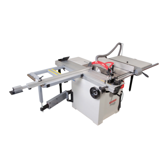
43-44-45-46-47-48-49-50-51-52-53-54 Notes Introduction The Axminster Trade MJ12-1600 MKII Panel Saw has been designed for the anywhere on the sliding table and has a telescopic fence 1,200-2,200mm long, trade workshop or keen home furniture maker. Upgraded over the previous enough for full size boards. This can easliy be removed without tools for stor- model with a high torque 2.2kW output mtor, a deeper section cast iron table,... -
Page 3: Table Of Contents
What’s Included Quantity Item Model Number 1 No MJ12-1600MkII Panel Saw (TRADE) MJ12-1600II BOX 1 Part BOX 2 Part 1 No Main Saw Assembly 1 1 No 1 No Sliding Table Extension Support Arm Sliding Table Assembly 1 No Rip Fence Control Assembly 2 1 No Rip Fence Rail Shaft 1 No... - Page 4 What’s Included Box 1...
- Page 5 What’s Included Box 1...
- Page 6 What’s Included Box 1 Box 2...
- Page 7 General Instructions for 230V Machines Good Working Practices/ Safety balanced, not reaching etc. If the work you are carrying out is liable to generate flying grit, dust or chips, wear the The following suggestions will enable you to observe appropriate safety clothing, goggles, gloves, masks etc. If good working practices, keep yourself and fellow the work operation appears to be excessively noisy, wear workers safe and maintain your tools and equipment...
- Page 8 Specification Code 505150 Model MJ12-1600 MKII Rating Trade Power 2.6kW (max input) 2.2kw output 230V 1ph Blade Dia/Bore 254, 305 or 315mm x 30mm x 3mm Blade Tilt 0-45°...
- Page 9 Initial Assembly PLEASE NOTE: Some of this assembly Fig 02- 03 procedure is best accomplished by two persons, some of the items are heavy and Phillips screw Extraction moulding awkward, and a mishandling error could cause injury. Please think about what you are doing, your capabilities and your personal safety.
- Page 10 Initial Assembly 3. Insert the other end of the hose (14) over the saw Fig 09-10 assembly’s dust housing outlet and secure with the re- maining hose clamp, see figs 05-06-07 Fig 05-06 Fig 07 Cap head screw & washer 5mm Hex key 6.
- Page 11 Initial Assembly Fig 12-13 Fig 15 Phillips screw & washer M8 Bolts & washers 3. Place a straight edge across both tables and check they are level with each other, see fig 16. If there is any deviation between the tables adjust the four grub screws below each M8 bolt, see fig 17.
- Page 12 Initial Assembly 7. Place a straight edge across the tables as before, adjust Fig 18 the table support leg (8) as described in step 6, until the pressed steel table (11) is level with the cast iron table (10), see fig 22-23. Once satisfied tighten all the bolts. Fig 22-23 Bolts, washers &...
- Page 13 Initial Assembly 2. Line up the threaded studs with the pre-drilled holes Fig 28-29 to the side of the tables and insert the studs into the holes, replace the nuts and washers you removed earlier and lightly tighten at this point, see fi g 24-25-26. Fig 25-26 Locking pin 5.
-
Page 14: Sliding Table Assembly
Initial Assembly 6. Raise the clamping handle on the control assembly (2) Fig 35-36 and position the rip fence so its in line with the edge of the main tables ‘T’ slot, push the handle down to lock in place, see fig 32. If the fence is out of alignment loosen Angled support bracket Fig 32 Main tables ‘T’... - Page 15 Initial Assembly Fig 43-44 ‘T’ bolt ‘T’ slot 3. Remove the four bolts and washers from the bottom corner of the main saw tables frame, see fig 40. Locate the extension support arm (1), line up the holes in the support bracket with the holes in the saw frame and secure with the bolts/washers you removed earlier, see fig 41.
- Page 16 Initial Assembly 6. Locate the sliding table support leg (7), locate the two Fig 49-50-51 ‘T’ bolts into the slots to the opposite end of the sliding table (19) and tighten the two nuts with the supplied spanner, see fig 46-47. Loosen the cap head screw on the support leg and lower the leg to the floor, retighten the screw, see fig 48.
- Page 17 Initial Assembly Fig 53 Fig 57-58 Fig 54-55-56 90˚ Square 10. Locate the Workpiece support shoe (4), insert the ‘T’ bolt into the ‘T’ slot to the left side of the sliding table (19), slide the shoe on and clamp in place with the clamping knob, see fig 60-61-62.
- Page 18 Initial Assembly 11. Locate the sliding table mitre fence (3), line up the Fig 67-68 ‘T’ bolt with the ‘T’ slot as before and slide the assembly onto the opposite side of the sliding table (19) until its up against it’s stop, see fig 62-63. The mitre fence should line up with ‘0’...
- Page 19 Initial Assembly 2. Slot the machined cutout to the end of the angled other. Tighten the two bolts to securely clamp the table bracket (6) over the threaded bolt beneath the table to in position, see fig 76. the side of the machine, see fig 71 and lightly tighten. Fig 74 Remove the bolt, washer/nut from beneath the table (12), line up the hole to the opposite end of the bracket...
- Page 20 Initial Assembly Crown Guard & Hose Fig 81-82 NOTE: Three sizes of saw bades can be fitted to this panel saw, 254mm, 305mm and 315mm. If you change your main blade to a different size make sure to attach the crown guard to the correct position in the riving knife to allow the crown guard to cover the blade, see fig 79.
- Page 21 Machine Footprint 2,900mm 1 Metre extension...
- Page 22 Machine Footprint Right Hand Extension Table Right Hand Table Rear Extension Table Sliding Table Extension Table 3,200mm Illustration and Parts Description Flexible hose Workpiece support shoe Blade Hose support bracket Rear extension table Sliding table extension Rip fence scale Distance stop assembly Out feed roller Right hand table...
-
Page 23: Rip Fence Rail Shaft
Illustration and Parts Description Riving knife Right hand extension table Sliding table fence Sliding table Right hand cast Rip fence iron table Work clamp Sliding table operating handle Sliding table Rip fence clamp mitre fence Rip fence assembly Main saw assembly Rip fence rail shaft Right hand table support leg... -
Page 24: Rip Fence
Illustration and Parts Description Main Saw table mitre fence, (A) Scale, (B) and pointer (C) Extension table 90˚ degree stop Press down the lever (D) to select a different angle Distance stop assembly For fine adjustment turn Rip fence scale, (A) Loosen the lift &... - Page 25 Illustration and Parts Description Telescopic fence extension, (A) and clamping knob, (B) Extension table angle adjusting bolts Angle support bracket for sliding table assembly • Rise and fall cap head screws (A) • Support bracket clamping bolts (B) Riving knife (A), Saw blade (B), Scoring blade, (C) Countersink hex screws, (D) to tighten the sliding table if slide play movement is apparent Inner cover micro switch Riving knife assembly...
-
Page 26: Workpiece Clamp Shaft
Illustration and Parts Description work clamp Adjuster lock Scoring blade Hex screw access holes Workpiece clamp shaft (22) with the work • Height adjuster, (A) clamp taken from the mitre fence assembly (3) • Left and right adjuster, (B) Scoring blade drive belt Saw blade drive belt Motor hold down bolts Saw tilt mechanism... - Page 27 Illustration and Parts Description Saw assembly tilted to 45˚ degrees Saw scale set to 45˚ degrees Saw assembly set at 90˚ degrees • Saw tilt scale (A) • Scale pointer (B) ON Button OFF Button Rise and fall operating wheel, (A) and clamping knob, (B) NVR ON/OFF switch assembly, (A) Emergency stop shroud, (B) press down to stop the machine...
- Page 28 Illustration and Parts Description Sliding extension table and fence assembly Table extension lift and shift Sliding table extension scale Micro adjuster locking grub screw clamping handle Twist Pull 45˚ degree operating wheel Sliding table locking knob...
- Page 29 Positioning the Machine Ascertain the orientation of the machine and move it to wish to machine. The machine should be positioned on its desired position in the workshop. Ensure that the a flat level surface. Manoeuvre the machine to the machine is positioned to allow sufficient clearance all chosen location making sure there is sufficient space all round to cater for the maximum length of timber you...
- Page 30 Setting Up the Machine Check that everything that should be tight, is tight; saw blade guard, rise and fall lock mechanism, fence clamps etc. Replace the crown guard assembly. Scoring blade Extension Table Fence Feeler gauge 1. Raise the blade to its maximum height, slacken the lift and shift handle (A) and the steel pin by loosening the clamping knob (B), see fig 93.
- Page 31 Setting Up the Machine 4. Using a steel rule measure 30mm back from the saw tip, so the scale on the rule lines up with the 30mm on the fence scale (23), see fig 99-100. Secure the fence 90˚ Stop cam again as described in step 1.
- Page 32 Setting Up the Machine 4. Once correct tighten nuts on the supporting brackets Fig 102 to the underside of the sliding table to lock the setting, see fig 98. Sliding Table Height Place a straight edge across both tables, see fig 106 loosen the two clamping bolts on the support brackets beneath the sliding table, see fig 107 and adjust the rise full cap head screws until the sliding table (19) is level...
-
Page 33: Rip Fence Scale
Setting Up the Machine Setting the Riving Knive Gap NOTE: Make sure you replace the inner guard over the micro switch, see fi g 112 1. Raise the saw blade up to it maximum height and otherwise the panel saw will not run. remove the crown guard assembly. -
Page 34: Operating Instructions
Operating Instructions Fig 116 CONNECT THE MACHINE TO THE MAINS! Connect the machine to the mains supply, give the machine a test run, by pressing the On/Off buttons. Check that everything sounds and feels O.K. (No knocking, scraping, belt squeal, rubbing etc). Switch off the machine, wait until the saw comes to a complete stop and disconnect the machine from the mains supply. - Page 35 Operating Instructions Fig 119 NOTE: DURING OPERATION IF YOU NOTICE A BUILD UP OF SAW DUST STOP THE MACHINE AND FOLLOW THE INSTRUCTIONS BELOW. 3. Wait until the saw has stopped and disconnect the machine from the mains supply. 4. Move the sliding table (19) to one side, using a vacuum cleaner clean out any build up of dust debris or resin then slide the table to the opposite side and repeat the procedure.
- Page 36 Operating Instructions 3. Start the saw, wait until it’s at full speed and carefully feed the workpiece through using a ‘Push Stick’ , (A). RECONNECT THE MACHINE TO THE MAINS! Make sure the workpiece is clear of the blade then turn off the saw, wait until the saw comes to a complete stop Start the saw by pressing the ‘ON’...
- Page 37 Changing the Saw Blade Changing the Main Blade WARNING!! DISCONNECT THE MACHINE FROM THE MAINS BEFORE CONTINUING! 1. Raise the saw blade to it’s highest point. Remove the Blade locking bar saw blade crown guard and place to one side. Pull the sliding table locking knob towards you and slide the table to the side exposing the blades.
- Page 38 Changing the Saw Blade 8. Replace the inner guard assembly, slide the table Fitting Scoring Blade Shims back until the locking knob pin engages the pin recess, The scoring blade comes in two parts to allow the shims turn the saw blade once by hand to check it spins freely (0.1-0.2-0.3mm) to be inserted between so that the cut and replace the crown guard.
-
Page 39: Routine Maintenance
Routine Maintenance General Information 2. Adjust each screw in turn, (one rotation) should be sufficient. Slide the table to the opposite end and repeat • Keep the saw as clean and free from saw dust the procedure. Check the table to see that the slide play build up as practical. - Page 40 Routine Maintenance 3. Remove the fixing that secures the extractor housing Fig 141 assembly, see figs 137-138-139 place them safely aside and lower housing assembly down to the floor. Fig 137-138-139 Cap head bolt 5. Remove the belt from the pulleys and check the condition of the belt.
- Page 41 Routine Maintenance 7. Replace the extractor housing, side panel (9), main Lubrication blade, inner guard, crown guard assembly and slide the After every three or four months we recommend you table (19) back until it locks in place. lubricate the blades and the tilt, rise and fall screw threads using ‘Ambersil Dry PTFE Film Antistick’...
-
Page 42: Wiring Diagram
Wiring Diagram Single Phase... - Page 43 Exploded Diagram/Parts List Diagram/List A A-22 Cover, switch box A-23 Plastic plate A-24 Strain relief A-25 Switch box A-28 Washer 4mm A-29 Pan head screw M4x12 A-30 Hold screw, push stick Part No Description A-31 Push stick Pan head screw M6x12 A-32 Internal guard Washer 6mm...
- Page 44 Exploded Diagram/Parts List Diagram/List B...
- Page 45 Exploded Diagram/Parts List Diagram/List B Part No B-44 Description Adjustable disc B-51 Star-type, lock handle Scew guide B-52 Flat washer 8mm Taping screw ST4.2x12 Hex screw M8x25 B-53 End cap, sliding panel Hex screw M8x40 B-54 Allen screw M5x8 Screw B-55 Sliding panel set T-base, adjust...
- Page 46 Exploded Diagram/Parts List Diagram/List C...
- Page 47 Exploded Diagram/Parts List Diagram/List C2 Continues Over..
- Page 48 Exploded Diagram/Parts List Diagram/List C /C2 Part C-36 C-73 Description Hex head screw M6X12 C-37 C-74 Belt guard Hex nut M8 Frame-blade C-38 C-75 Thread Pan head screw M6X12 Shaft-main blade C-39 Shaft, spring C-76 Flat washer 6mm Main shaft C-40 Insert C-77...
- Page 49 Exploded Diagram/Parts List Diagram/List D Part No D-13 Description Thread bushing D-14 L type aluminum baffle Washer M5 Locking plate D-15 Countersunk head screw M5X16 The positioning shaft D-16 The locking block mandrel Countersunk head screw M5X16 D-17 Inner six angle locking Connecting plate D-18 Locking block...
- Page 50 Exploded Diagram/Parts List Diagram/List E...
- Page 51 Exploded Diagram/Parts List Diagram/List E Part No E-41 Description Support, swing arm E-42 Scale, cross cut table Hex screw M8x30 E-43 Washer 6mm Hex screw M 10x25 Scale, cross cut table E-44 Sunk head#screw M6x12 Allen screw M6x12 E-45 T-nut, extension fence Eccentric cam E-46 Lock plate...
- Page 52 Exploded Diagram/Parts List Diagram/List G...
- Page 53 Exploded Diagram/Parts List Diagram/List G Part No G-20 Description Dust hose support G-21 Rear extension table Washer 6mm G-22 Washer 8mm Hex screw M6x20 Hex nut M8 G-23 Hex nut M6 Set screw M6x12 G-26 Adjustable disc Hex screw M8x16 G-27 Lower, support Flat washer 10mm...
- Page 54 Exploded Diagram/Parts List Diagram/List H Description Gauge fence Mitre gauge knob Sunk head screw M5x8 Washer 6mm Roller, gauge Mitre gauge base H-10 Carriage bolt M6x32 Indicator H-11 Mitre gauge rod Screw H-12 Washer 6mm End cap, Gauge fence H-13 Knurled nut...
- Page 55 Notes...
- Page 56 The Axminster guarantee is available on Hobby, Trade, Industrial, Engineer, Air Tools & CNC Technology Series machines It’s probably the most comprehensive FREE guarantee ever- buy with confidence from Axminster! So sure are we of the quality, we cover all parts and labour free of charge for three years! •...
Need help?
Do you have a question about the MJ12-1600 MKII and is the answer not in the manual?
Questions and answers