Table of Contents
Advertisement
Quick Links
FBM034 and FBM034W Fieldbus Input Modules
Application
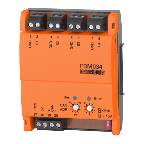
With four analog inputs, fieldbus input modules FBM034 und
FBM034W record the signals of remote devices in DDC3000 and
DDC4000 controllers.
The analog inputs can be set to either DC 0-10 V or KP10. LEDs
are used for communication monitoring.
Data is transferred between the controller and the input module
over the fieldbus.
Content
Important Information Regarding Product Safety ..................................................................................................2
Item........................................................................................................................................................................3
Technical Data.....................................................................................................................................................3
Accessories .........................................................................................................................................................4
Dimensions ..........................................................................................................................................................4
Connection.............................................................................................................................................................5
Installation..............................................................................................................................................................6
Mounting ................................................................................................................................................................6
Mounting the Cascade Plug.................................................................................................................................7
Removal.................................................................................................................................................................8
Commissioning ......................................................................................................................................................8
Function/Operation ..............................................................................................................................................9
LED Display for Bus/Error....................................................................................................................................9
Kieback&Peter GmbH & Co. KG
Tempelhofer Weg 50, 12347 Berlin/Germany
Telefon: +49 30 60095-0, Telefax: +49 30 60095-164
www.kieback-peter.de, info@kieback-peter.com
J
Product Description
FBM034, FBM034W
Page
2.50-30.034-31-EN | 2019-11-04
Advertisement
Table of Contents

Related Manuals for Kieback&Peter FBM034

Summary of Contents for Kieback&Peter FBM034
-
Page 1: Table Of Contents
FBM034, FBM034W FBM034 and FBM034W Fieldbus Input Modules Application With four analog inputs, fieldbus input modules FBM034 und FBM034W record the signals of remote devices in DDC3000 and DDC4000 controllers. The analog inputs can be set to either DC 0–10 V or KP10. LEDs are used for communication monitoring. -
Page 2: Important Information Regarding Product Safety
Important Information Regarding Product Safety Safety Instructions This data sheet contains information on installing and commissioning the product "FBM034, FBM034W". Each person who carries out work on this product must have read and understood this data sheet. If you have any questions that are not resolved by this data sheet, you can obtain further information from the supplier or manufacturer. -
Page 3: Item
Ambient humidity 20%..80% r.h., non-condensing Installation On standard TH 35 x 7.5 rails for installation in the control panel or the wall-mounted enclosure. Weight FBM034 0.13 kg; FBM034W 0.8 kg Sensor types Sensor type Value range 0 V.. 10 V 0%..100% KP10 -50 °C...150 °C... -
Page 4: Accessories
Product Description FBM034, FBM034W Accessories Not included in delivery. Z179 Cascade plug Multiple FBM0xx modules can be connected using the cascade plug. In this manner, the modules are supplied even when there are- inactive modules within the chain. Connected fieldbus lines: DC 12 V, DC 0 V; CAN bus (+, -) A maxi- mum of 5 modules can be connected in cascade. -
Page 5: Connection
Product Description FBM034, FBM034W Connection CAUTION The GND wiring specified in the wiring diagram (Y GND, K GND, B GND) must be observed. Incorrect GND wiring may lead to errors in measurement. KP10 B1..B4: KP10 KP10 KP10 KP10 KP10 0..10V KP10 B1..B4: 0..10V=... -
Page 6: Installation
Product Description FBM034, FBM034W Installation CAUTION This product description describes specific settings and functions of the FBM034x. In addition to these instructions, observe the product descriptions of other system components, such as DDC controller DDC4000, BMR or DDC420. CAUTION Switching on the power supply of unparameterized products can lead to unforeseen consequences such as malfunctions or material damage. -
Page 7: Mounting The Cascade Plug
Product Description FBM034, FBM034W Mounting the Cascade Plug ■ Remove the covers of the devices that are to be cascaded by releasing the catches using the two slots that are provided and lifting off the covers. ■ Snap the device base onto the standard rail and slide the units together. -
Page 8: Removal
Product Description FBM034, FBM034W Removal Commissioning CAUTION Commissioning by switching on the supply voltage may occur only after the commissioning technician/engineer has finished configuring the DDC and has set the bus address. ■ Configuration is described in the DDC controller project planning documentation. -
Page 9: Function/Operation
Product Description FBM034, FBM034W Function/Operation Green LED Red LED Address switch – address setting 01 to 63 Measuring range switch inputs can be set to 0–10 V or KP10 Setting the address Address settings: 01 to 63 Example: 15 LED Display for Bus/Error... - Page 10 Product Description FBM034, FBM034W 2.50-30.034-31-EN | 2019-11-04 Page 10 / 10...
Need help?
Do you have a question about the FBM034 and is the answer not in the manual?
Questions and answers