Table of Contents
Advertisement
Quick Links
FBU410 Input/ Output Modulel
Application
The FBU410 Ein-Ausgabe-Modul with 4 relay outputs
and 6 universal inputs/outputs controls and records the
signals of remote devices in the DDC4000 system and on
the BMR.
Data is transferred between the DDC controller and the
input/output module via the fieldbus.
The function of the 6 universal inputs/outputs can be
individually configured and defined for each connection.
Content
Important Information on Product Safety ...............................................................................................................2
Item........................................................................................................................................................................3
Technical Data.....................................................................................................................................................3
Accessories (not included in delivery) .................................................................................................................4
Dimensions ..........................................................................................................................................................4
Installation..............................................................................................................................................................5
Connection...........................................................................................................................................................6
Mounting ................................................................................................................................................................7
Removal...............................................................................................................................................................8
Commissioning ......................................................................................................................................................8
Function/Operation ..............................................................................................................................................9
Setting the Fieldbus Address...............................................................................................................................9
LED Display for Bus/Error..................................................................................................................................10
Kieback&Peter GmbH & Co. KG
Tempelhofer Weg 50, 12347 Berlin/Germany
Telefon: +49 30 60095-0, Telefax: +49 30 60095-164
www.kieback-peter.de, info@kieback-peter.com
J
Product description
FBU410
Page
2.50-30.410-01-EN | 2022-07-18
Advertisement
Table of Contents

Related Manuals for Kieback&Peter FBU410

Summary of Contents for Kieback&Peter FBU410
-
Page 1: Table Of Contents
Product description FBU410 FBU410 Input/ Output Modulel Application The FBU410 Ein-Ausgabe-Modul with 4 relay outputs and 6 universal inputs/outputs controls and records the signals of remote devices in the DDC4000 system and on the BMR. Data is transferred between the DDC controller and the input/output module via the fieldbus. -
Page 2: Important Information On Product Safety
Important Information on Product Safety Safety instructions This document contains information on installing and commissioning the product “FBU410”. Each person who carries out work on this product must have read and understood this document. If you have any questions that are not resolved by this document, you can obtain further information from the supplier or manufacturer. -
Page 3: Item
Product description FBU410 Item FBU410 Input/ output module Technical Data Nominal voltage DC 12 V ± 20%, 2.0 W Inputs and outputs 4 binary outputs; potential-free relay contact max. AC 230 V / 5 (3) A 6 universal inputs/outputs that can be independently configured as: - Binary output Transistor output DC 24 V;... -
Page 4: Accessories (Not Included In Delivery)
Product description FBU410 Sensor types Sensor type Measuring range 0(2) V..10 V 0%..100% KP10 -50 °C..+150 °C KP250 -50 °C..+150 °C -50 °C..+150 °C Ni100 -50 °C..+150 °C Ni1000 (DIN) -50 °C..+150 °C Ni1000 (L&G) -50 °C..+150 °C NTC1,8K -50 °C..+150 °C NTC5K -50 °C..+150 °C... -
Page 5: Installation
Product description FBU410 Installation CAUTION This product description describes specific settings and functions of the FBU410. In addition to these instructions, observe the product descriptions of other system components, such as DDC controller DDC4000, BMR or DDC420. CAUTION Switching on the power supply of unparameterized products can lead to unforeseen consequences such as malfunctions or material damage. -
Page 6: Connection
Product description FBU410 Connection CAUTION The GND wiring specified in the wiring diagram (Y GND, K GND, B GND) must be observed. Incorrect GND wiring may lead to errors in measurement. 5 (3) A 5 (3) A 5 (3) A... -
Page 7: Mounting
Product description FBU410 Mounting WARNING Contact with live parts of electrical domestic installation can cause death due to electric shock. Mounting/removal may only be carried out when power is switched off. Mounting without cascade plug Installation with Z179 cascade plug accessory (not included in the scope of delivery) -
Page 8: Removal
Product description FBU410 Removal WARNING Contact with live parts of electrical domestic installation can cause death due to electric shock. Mounting/removal may only be carried out when power is switched off. Commissioning CAUTION Commissioning by switching on the supply voltage may occur only after the commissioning technician/engineer has finished configuring the DDC and has set the bus address. -
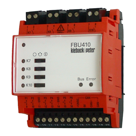
Page 9: Function/Operation
Product description FBU410 Function/Operation Operating and display elements under the transparent cover (transparent cover not shown in the figure) Front panel LED red/green/yellow (solid/flashing), can be freely configured 4 green LEDs for indicating outputs K7 to K10 4 manual switches for the digital outputs K7 to K10... -
Page 10: Led Display For Bus/Error
Product description FBU410 LED Display for Bus/Error LED bus (8) LED error (9) Meaning Cause Green Module not in ■ No operating voltage or operating operation voltage too low Module in opera- ■ Bus line short circuit (with respect to...
Need help?
Do you have a question about the FBU410 and is the answer not in the manual?
Questions and answers