
Related Manuals for Mitsubishi Electric Mr. Slim MVZ Series


Summary of Contents for Mitsubishi Electric Mr. Slim MVZ Series
- Page 1 SPLIT-TYPE, HEAT PUMP AIR CONDITIONERS 2015 SERVICE MANUAL Series MVZ Model name Model name <Indoor unit> <Indoor unit> MVZ-A12AA4 MVZ-A18AA4 MVZ-A24AA4 MVZ-A30AA4 MVZ-A36AA4 INDOOR UNIT...
-
Page 3: Table Of Contents
ONTENTS . SAFETY PRECAUTION 2. PART NAMES AND FUNCTIONS 3. SPECIFICATION 4. FAN PERFORMANCE AND CORRECTED AIR FLOW 5. SOUND PRESSURE LEVELS 6. OUTLINES & DIMENSIONS 7. WIRING DIAGRAM 8. REFRIGERANT SYSTEM DIAGRAM 9. HEATER CONTROL 0. HUMIDIFIER CONTROL . ERV (ENERGY RECOVERY VENTILATION) CONTROL 2. -
Page 4: Safety Precaution
SAFETY PRECAUTION 1-1. ALWAYS OBSERVE FOR SAFETY Before obtaining access to terminal, all supply circuits must be disconnected. 1-2. CAUTIONS RELATED TO NEW REFRIGERANT Cautions for units utilising refrigerant R410A Use new refrigerant pipes. Do not use refrigerant other than R410A. In case of using the existing pipes for R22, be careful with If other refrigerant (R22 etc.) is used, chlorine in refrige- the followings. -
Page 5: Part Names And Functions
Unit Gravimeter [3] Service tools Use the below service tools as exclusive tools for R410A refrigerant. Tool name Specifications Gauge manifold Only for R410A · Use the existing fitting specifications. (UNF1/2) · Use high-tension side pressure of 5.3MPa·G or over. ·... -
Page 6: Specification
(3)Horizontal left (4)Down flow Air inlet inlet outlet Air outlet SPECIFICATION Service Ref. MVZ-A12AA4 Power supply (phase, cycle, voltage) 1 phase, 60Hz, 208/230V Max. Fuse Size Min. Circuit Ampacity 3.00 External finish Galvanized steel cabinet - Powder coated Slate Gray Heat exchanger Plate fin coil Fan (drive) ×... - Page 7 Service Ref. MVZ-A24AA4 Power supply (phase, cycle, voltage) 1 phase, 60Hz, 208/230V Max. Fuse Size Min. Circuit Ampacity 3.00 External finish Galvanized Steel Cabinet - Powder coated Slate Gray Heat exchanger Plate fin coil Fan (drive) × No. Sirocco fan × 1 an motor output 0.121 F.L.A...
-
Page 8: Fan Performance And Corrected Air Flow
FAN PERFORMANCE AND CORRECTED AIR FLOW MVZ-A12AA4 • Vertical, Horizontal Right, Horizontal Left • Downflow External static pressure 0.30 [in.WG] (75Pa) 208/230V 60Hz External static pressure 0.30 [in.WG] (75Pa) 208/230V 60Hz [0.40] [0.40] High [0.30] [0.30] High Middle Middle [0.20] [0.20] [0.10] [0.10]... - Page 9 MVZ-A18AA4 • Vertical, Horizontal Right, Horizontal Left • Downflow External static pressure 0.30 [in.WG] (75Pa) 208/230V 60Hz External static pressure 0.30 [in.WG] (75Pa) 208/230V 60Hz [0.40] [0.40] High [0.30] [0.30] High Middle [0.20] [0.20] Middle [0.10] [0.10] [353] [530] [706] [353] [530] [706]...
- Page 10 MVZ-A24AA4 • Vertical, Horizontal Right, Horizontal Left • Downflow External static pressure 0.30 [in.WG] (75Pa) 208/230V 60Hz External static pressure 0.30 [in.WG] (75Pa) 208/230V 60Hz [0.40] [0.40] High [0.30] [0.30] High Middle [0.20] [0.20] Middle [0.10] [0.10] [459] [530] [706] [847] [459] [530]...
- Page 11 MVZ-A30AA4 • Vertical, Horizontal Right, Horizontal Left • Downflow External static pressure 0.30 [in.WG] (75Pa) 208/230V 60Hz External static pressure 0.30 [in.WG] (75Pa) 208/230V 60Hz [0.40] [0.40] High High [0.30] [0.30] Middle Middle [0.20] [0.20] [0.10] [0.10] [530] [706] [883] [1024] [530] [706]...
- Page 12 MVZ-A36AA4 • Vertical, Horizontal Right, Horizontal Left • Downflow External static pressure 0.30 [in.WG] (75Pa) 208/230V 60Hz External static pressure 0.30 [in.WG] (75Pa) 208/230V 60Hz [0.40] [0.50] High [0.40] [0.30] High Middle [0.30] Middle [0.20] [0.20] [0.10] [0.10] [671] [706] [883] [1059] [1165]...
- Page 13 MVZ-A12, 18, 24, 30, 36AA4 Air filter Power source:208/230V 60Hz [0.100] [0.080] A30,36 A30,36 [0.060] A12,18,24 A12,18,24 [0.040] [0.020] [353] [706] [1059] [1412] [1766] Airflow rate (m /min)[cfm]...
-
Page 14: Sound Pressure Levels
SOUND PRESSURE LEVELS 5-1. Sound pressure level Ceiling concealed ux.duct Front side 3-1/4ft. (1m) Measurement location ux.duct 5-2. NC curves MVZ-A12AA4 MVZ-A18AA4 External static pressure 0.30 [in.WG] (75Pa) External static pressure 0.30 [in.WG] (75Pa) 70.0 70.0 High High Middle Middle 65.0 65.0 60.0... - Page 15 MVZ-A24AA4 MVZ-A30AA4 External static pressure 0.30 [in.WG] (75Pa) External static pressure 0.30 [in.WG] (75Pa) 70.0 70.0 High High Middle Middle 65.0 65.0 60.0 60.0 NC-60 NC-60 55.0 55.0 50.0 50.0 NC-50 NC-50 45.0 45.0 40.0 40.0 NC-40 NC-40 35.0 35.0 30.0 30.0 NC-30...
- Page 16 MVZ-A36AA4 External static pressure 0.30 [in.WG] (75Pa) 70.0 High Middle 65.0 60.0 NC-60 55.0 50.0 NC-50 45.0 40.0 NC-40 35.0 30.0 NC-30 25.0 20.0 Approximate minimum NC-20 audible limit on continuous noise Octave band center frequencies (Hz) External static pressure 0.50 [in.WG] ( 25Pa) 70.0 High Middle...
-
Page 17: Outlines & Dimensions
OUTLINES & DIMENSIONS INDOOR UNIT MVZ-A12, 18, 24, 30, 36AA4... -
Page 19: Wiring Diagram
WIRING DIAGRAM MVZ-A12, 18, 24, 30, 36AA4 TRANSMISSION WIRES DC 12V INSIDE SECTION OF CONTROL BOX TB15 R.B. REMOTE CONTROLLER I.B. OPTIONAL PARTS CN32 TO OUTDOOR UNIT (RED) (BLUE) CN105 CN3C P.B. LED2 (RED) (BLACK) CN90 CN2A CN41 (RED) CN25 (BLUE) CNER CN22... -
Page 20: Refrigerant System Diagram
REFRIGERANT SYSTEM DIAGRAM MVZ-A12, 18, 24, 30, 36AA4 Strainer (#50) Heat exchanger Refrigerant GAS pipe connection (Flare) Thermistor TH5 (Cond./ Eva.temperature) Refrigerant flow in cooling Refrigerant flow in heating Thermistor TH2 Pipe temperature(Liquid) Refrigerant LIQUID pipe connection (Flare) Thermistor TH1 (Room temperature) Strainer (#50) Distributor... -
Page 21: Heater Control
HEATER CONTROL 9-1. CONTROL SPECIFICATIONS AND FUNCTION SETTING Table 1 shows how the field-installed heater is controlled. Select the desired pattern in the table below, and set the Function on the indoor units as shown in Table 1. Table.1 [Function table] Select unit numbers 01 to 03 or all units (AL [wired remote controller] / 07 [IR wireless remote controller]) Setting ode (function) No. - Page 22 9-2. FAN CONTROL By setting the Mode No. 23 in the Function Table in section 9-1, the following patterns of fan control will become possible. Fan control patterns Fan in defrost Fan(All modes other Factory CN4Y for FAN control Mode(function) (PAC-YU25HT) No.23(123) than defrost)
- Page 23 (3) Locally procured wiring A basic connection method is shown below. Indoor unit Remote control board Relay circuit control board Adapter CN24-1 or CN24-2 White Electric Heater or panel heater Maximum cable length Preparations in the field is 10 m (32ft) For relay X use the specifications given below Operation coil Rated voltage: 12VDC Power consumption: 0.9W or less...
-
Page 24: Humidifier Control
HUMIDIFIER CONTROL 10-1. CONTROL SPECIFICATIONS The below table shows how the field installed humidifier and fan speed is controlled. Mode (function) No. Humidistat Condition (no defrost/no error) CN25 output Fan speed output Wired remote controller (RF thermostat) 13 (113) 16 (116) CNF input Heat operation &... -
Page 25: Erv (Energy Recovery Ventilation) Control
ERV (ENERGY RECOVERY VENTILATION) CONTROL 11-1. CONTROL SPECIFICATIONS The below table shows how the field installed ERV is controlled. ERV output Condition Fan speed CN2C output (=Fan output) CNER input Cool/Heat/Fan operation RC setting Defrost STOP STOP STOP Cool/Heat/Fan operation RC setting Defrost STOP... -
Page 26: Troubleshooting
TROUBLESHOOTING 12-1. CAUTIONS ON TROUBLESHOOTING (1) Before troubleshooting, check the followings: 1 Check the power supply voltage. 2 Check the indoor/outdoor connecting wire for mis-wiring. (2) Take care the followings during servicing. 1 Before servicing the air conditioner, be sure to turn off the remote controller first to stop the main unit, and then turn off the breaker. - Page 27 12-2. SELF-CHECK FUNCTION • Refer to the installation manual that comes with each remote controller for details. • RF thermostat is not established. [Output pattern A] Errors detected by indoor unit Wired remote controller IR wireless remote controller RF thermostat Symptom Remark Beeper sounds/OPERATION...
- Page 28 For description of each LED (LED1, 2, 3) provided on the indoor controller, refer to the following table. LED 1 (power for microcomputer) Indicates whether control power is supplied. Make sure that this LED is always lit. LED 2 (power for remote controller) Indicates whether power is supplied to the remote controller.
- Page 29 Note: Refer to the manual of outdoor unit for the details of display 12-3. SELF-DIAGNOSIS ACTION TABLE such as F, U, and other E. Abnormal point and detection method Countermeasure Error Code Cause Room temperature 1 Defective thermistor 1–3 Check resistance value of thermistor. thermistor (TH1) characteristics 0:[32˚F]..15.0k"...
- Page 30 Abnormal point and detection method Countermeasure Error Code Cause Freezing/overheating protection is (Cooling or drying mode) (Cooling or drying mode) working 1 Clogged filter (reduced airflow) 1 Check clogging of the filter. 1 Freezing protection (Cooling mode) 2 Short cycle of air path 2 Remove shields.
- Page 31 Abnormal point and detection method Countermeasure Error Code Cause Abnormality of pipe temperature ther- 1 Defective thermistor 1–3 Check resistance value of thermistor. mistor / Condenser-Evaporator (TH5) characteristics For characteristics, refer to (P1) above. 2 Check contact failure of connector (CN44) 1 The unit is in three-minute resume pro- 2 Contact failure of connector on the indoor controller board.
- Page 32 Abnormal point and detection method Countermeasure Error Code Cause ∗ Check LED display on the outdoor control cir- Indoor/outdoor unit communication 1 Contact failure, short circuit or, error (Signal receiving error) cuit board. (Connect A-control service tool, mis-wiring (converse wiring) of 1 Abnormal if indoor controller board PAC-SK52ST.) indoor/outdoor unit connecting...
- Page 33 12-4. TROUBLESHOOTING BY INFERIOR PHENOMENA Note: Refer to the manual of outdoor unit for the detail of remote controller. Phenomena Cause Countermeasure (1)LED2 on indoor controller board • When LED1 on indoor controller board is also off. is off. 1 Power supply of rated voltage is not supplied to out- 1 Check the voltage of outdoor power door unit.
- Page 34 12-5. TEST POINT DIAGRAM 12-5-1. Power supply board MVZ-A12AA4 MVZ-A18AA4 MVZ-A24AA4 MVZ-A30AA4 MVZ-A36AA4 Power supply voltage (208 - 230VAC) CNMF Fan motor output 1 - 4: 310 - 340 VDC 5 - 4: 15 VDC 6 - 4: 0 - 6.5 VDC 7 - 4: Stop 0 or 15 VDC Run 7.5 VDC (0 - 15 pulse)
- Page 35 12-5-2. Indoor controller board MVZ-A12AA4 Emergency operation MVZ-A18AA4 MVZ-A24AA4 Model selection MVZ-A30AA4 Capacity setting MVZ-A36AA4 CN105 Radio frequency interface CN105 CN22 CN32 Remote start/stop adapter CN22 For MA remote controller cable con- CNXA2 nection (10 - 13 VDC) CN25 CNXC2 CN51 Centralized control CNER CNXB2...
- Page 36 12-6. TROUBLE CRITERION OF MAIN PARTS MVZ-A12AA4 MVZ-A18AA4 MVZ-A24AA4 MVZ-A30AA4 MVZ-A36AA4 Part name Check method and criterion Room temperature Measure the resistance with a tester. thermistor (Part temperature 10°C (50°F) ~ 30°C (86°F)) (TH1) Normal Abnormal Pipe temperature 4.3kΩ~9.6kΩ Opened or short-circuited thermistor/liquid (TH2) Condenser/evaporator...
- Page 37 12-8. DC FAN MOTOR (FAN MOTOR/INDOOR CONTROLLER BOARD) Check method of DC fan motor (fan motor/indoor controller circuit board) Notes · High voltage is applied to the connecter (CNMF) for the fan motor. Give attention to the service. · Do not pull out the connector (CNMF) for the motor with the power supply on. board and fan motor.) (It causes trouble of the indoor controller circuit Self check...
- Page 38 12-9. FUNCTIONS OF DIP SWITCH AND JUMPER WIRE Each function is controlled by the dip switch and the jumper wire on control p.c. board. SW1 and SW2 are equipped only for service parts. Model setting and capacity setting are memorized in the nonvolatile memory of the control p.c. board of the unit.
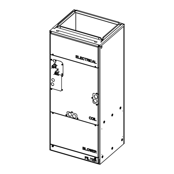
- Page 39 DISASSEMBLY PROCEDURE 1. Control box Exercise caution when removing heavy parts. 1. Remove the Electric panel (2 screws) 2. Remove the Control box cover (1 screw) Fig. 1 Fig. 2...
- Page 40 2. Thermistor (Return Air) Exercise caution when removing heavy parts. 1. Remove the Filter panel (2 thumbscrews). 2. Remove the Blower panel (2 screws). Fig. 3 3. Remove the cover over the Return Air thermistor box and unplug the thermistor. 4.
- Page 41 3. Coil Assembly Exercise caution when removing heavy parts. 1. Remove the Electrical, Blower and Filter panel indicated in sections 1 and 2. 2. Remove the Coil panel by removing all of the screws securing it to the (3) smaller panels for refrigerant and drain lines.
- Page 42 5. Remove the plate covering the coil assembly to access the thermistors. Fig. 9 6. Remove lower and side drain pan. Fig. 10...
- Page 43 4. Blower/Fan Assembly Exercise caution when removing heavy parts. 1. Remove the Blower and Filter panel (along with filter if installed) indicated in section 2. 2. Remove the (1 or 2) brackets that secure the coil assembly. Fig. 11 3. Remove the door that covers the small enclosure attached to the fan assembly (Fig.12).
- Page 44 http://Global.MitsubishiElectric.com New publication effective Feb. 2015 Specifications subject to change without notice HWE1407A...
Need help?
Do you have a question about the Mr. Slim MVZ Series and is the answer not in the manual?
Questions and answers