Table of Contents
Advertisement
Quick Links
Advertisement
Table of Contents

Related Manuals for TechVision NS4P1P8


Summary of Contents for TechVision NS4P1P8
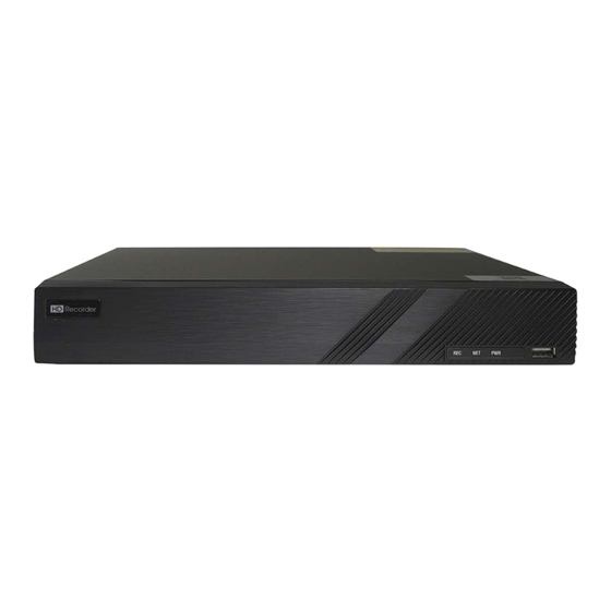
- Page 1 NS4P1P8 4 Channel Recorder 1U...
- Page 2 Notes Please read this user manual carefully to ensure that you can use the device correctly and safely. There may be several technically incorrect places or printing errors in this manual. The updates will be added into the new version of this manual. The contents of this manual are subject to change without notice.
-
Page 3: Table Of Contents
NVR User Manual Contents Contents _Toc515462999 Introduction ........................1 1.1 Summary ........................1 1.2 Features ......................... 1 1.3 Front Panel Descriptions ....................4 1.4 Rear Panel Descriptions ....................5 1.5 Connections ........................8 Basic Operation Guide ....................11 2.1 Startup & Shutdown ....................11 2.1.1 Startup ...................... - Page 4 NVR User Manual Contents 5.4.5 Image Adjustment .................... 45 PTZ ..........................48 6.1 PTZ Control Interface Introduction ................48 6.2 Preset Setting ....................... 51 6.3 Cruise Setting ......................52 Record & Disk Management ..................54 7.1 Record Configuration ....................54 7.1.1 Mode Configuration ..................
- Page 5 NVR User Manual Contents 9.4.1 IPC Offline Settings ..................85 9.4.2 Exception Handling Settings ................85 9.5 Alarm Event Notification .................... 86 9.5.1 Alarm-out ......................86 9.5.2 E-mail ....................... 86 9.5.3 Display ......................86 9.5.4 Buzzer ......................87 9.5.5 Push Message ....................87 9.6 Manual Alarm ......................
- Page 6 NVR User Manual Contents 12.3.1 Face Comparison ..................115 12.3.2 Face Match Alarm Settings ................116 12.4 Face Search and Playback ..................117 12.5 Smart Playback by Face Search ................121 Remote Surveillance ....................123 13.1 Mobile Client Surveillance ..................123 13.2 Web LAN Access ....................
-
Page 7: Introduction
NVR User Manual Introduction 1 Introduction 1.1 Summary Based on the most advanced SOC technology and embedded system in the field, this series of the NVR adopt the new designed human interface and support the smart management of the IP camera and the record search of slice. - Page 8 NVR User Manual Introduction Support multiple popular P.T.Z. control protocol and setup of the preset and cruise Support direct mouse control of the IP dome including rotating, zoom, focusing and so on Support single camera image to be zoomed by sliding the scroll wheel of the mouse ...
- Page 9 NVR User Manual Introduction 1/32 times of the normal speed) and 30s’ addition or reduction to current playing time Record Backup Support record to be backed up through USB (U disk, mobile HDD) or e-SATA interface Support record to be backed up by time/event/image searching ...
-
Page 10: Front Panel Descriptions
NVR User Manual Introduction The NVR can be controlled and operated by the buttons on the front panel, the remote controller and the mouse Setting interfaces can be switched to one another conveniently by clicking the main menus on the top of the setting interfaces ... -
Page 11: Rear Panel Descriptions
NVR User Manual Introduction Name Descriptions Manually record Play/Pause Speed down Speed up Input digital number and select camera 0/-- Input number 0, the number above 10 Direction Key Change direction Multi-Screen Switch Change the screen mode Enter Confirm selection To connect external USB device like USB mouse or USB flash 1.4 Rear Panel Descriptions... - Page 12 NVR User Manual Introduction Name Descriptions Connect to monitor e-SATA Connect to HDD with e-SATA interface Connectors for speed dome. Y is TX+, Z is TX- RS485 Y/Z interface (This interface of some models is unavailable.) RS485 A/B interface Connect to a keyboard. A is TX+; B is TX- AUDIO OUT Audio output;...
- Page 13 NVR User Manual Introduction Name Descriptions Connect to monitor Connect to speed dome. Y is TX+, Z is TX- RS485 Y/Z interface (This interface of some models is unavailable.) ALARM OUT Relay output; connect to external alarm Grounding AUDIO OUT Audio output e-SATA1/ e-SATA2 Connect to HDD with e-SATA interface...
-
Page 14: Connections
NVR User Manual Introduction Name Descriptions e-SATA Connect to HDD with e-SATA interface LAN1/LAN2 Network port Connect to 1920× 1080 high definition display device. HDMI2 Connect to monitor as an AUX output channel by channel. Only video display, no menu show USB interface, connect USB storage device or USB mouse HDMI1... - Page 15 NVR User Manual Introduction Audio Output: Connect to headphone, sound box or other audio output devices. Alarm Connections Some models may not support this function. Take 16 CH alarm inputs and 1 CH alarm output for example. Alarm Input: Alarm IN 1~16 are 16 CH alarm input interfaces.
- Page 16 NVR User Manual Introduction connect the power supply as per the following figures. RS485 Connection There are two types of RS485 interfaces: (Type 1) (Type 2) Type 1: The P/Z interfaces are unavailable temporarily. K/B interfaces are used to connect keyboard.
-
Page 17: Basic Operation Guide
NVR User Manual Basic Operation Guide 2 Basic Operation Guide 2.1 Startup & Shutdown Please make sure all the connections are done properly before you power on the unit. Proper startup and shutdown are crucial to expending the life of your device. 2.1.1 Startup ①... - Page 18 NVR User Manual Basic Operation Guide Button Function Switch off—to stop the device Power Button Record Button To start recording -/-- /0-9 Input number or choose camera Fn1 Button Unavailable temporarily Multi Button To choose multi screen display mode Next Button To switch the live image To go to sequence view mode Audio...
-
Page 19: Mouse Control
NVR User Manual Basic Operation Guide Button Function Record manually Search To enter search mode MEUN To enter menu Exit To exit the current interface ENTER To confirm the choice or setup Direction button To move cursor in setup ZOOM To zoom in No function temporarily To control playback. -
Page 20: Common Button Operation
NVR User Manual Basic Operation Guide The system includes two input boxes. Refer to the above pictures. The left box is the number input box and the right box is the input box which provides inputs of numbers, letters and punctuation characters. -
Page 21: Wizard & Main Interface
NVR User Manual Wizard & Main Interface 3 Wizard & Main Interface 3.1 Startup Wizard The disk icons will be shown on the top of the startup interface. You can view the number and status of each disk quickly and conveniently through these icons ( : no disk; : unavailable disk;... - Page 22 NVR User Manual Wizard & Main Interface Click “Edit Security Question” to set questions and answers for password security of admin. If you forget the password, please refer to Q4 in Appendix A FAQ for details. Click “Next” to continue or click “Cancel” to exit the wizard. ②...
- Page 23 NVR User Manual Wizard & Main Interface Note: If you use the NVR with the PoE network ports, the online state of the internal Ethernet port will be shown on the interface. Refer to the picture below. Please refer to 11.1.1 TCP/IP Configuration for detail introduction of the internal Ethernet port.
- Page 24 NVR User Manual Wizard & Main Interface...
- Page 25 NVR User Manual Wizard & Main Interface ④ Add Camera. Click “Refresh” to refresh the list of online IP cameras which are in the to add the searched camera. Click “Add same local network with NVR and then click to delete the added camera. Click “Delete All”...
- Page 26 NVR User Manual Wizard & Main Interface Click to edit the searched IP camera as shown on the below left. Input the new IP address, subnet mask, gateway, username and the password of the camera. You can check “Sync to IPC” to modify the IP address of the IPC via different network segments for being in the same network segment with the NVR.
-
Page 27: Main Interface
NVR User Manual Wizard & Main Interface Manual: Set the “Sensor Record”, “Motion Record” and “Schedule Record” of each camera. Click “OK” to save the settings. See 7.1.1 Mode Configuration for details. ⑨ QRCode. Enable the NAT function in the interface or set it in the network configuration after exiting the wizard (please refer to 11.1.7 NAT Configuration for details). - Page 28 NVR User Manual Wizard & Main Interface The buttons in area ① are introduced in the table below. Button Meaning Start button. Click it to pop up area ③. Full screen button. Click it to show full screen; click it again to exit the full screen.
-
Page 29: Setup Panel
NVR User Manual Wizard & Main Interface Button Meaning Information button. Click it to view system information. Introduction of area ②: Area ② is hidden by default. Move the cursor to the right to reveal this area. Click “Camera” to view all the added cameras in the camera list. Select one camera window on the left side of the interface and then double click one camera in the list to preview the camera image in the selected window. - Page 30 NVR User Manual Wizard & Main Interface The setup panel includes seven modules. Each module provides some function entries with links for convenient operation. Here we take Camera module as an example. The Camera module provides convenient links such as “Add Camera”, “Edit Camera”, “Image Settings”, “Motion”, “Intelligence Analysis” and “PTZ”.
-
Page 31: Main Functions
NVR User Manual Wizard & Main Interface the window as shown below. Click the main menus on the top of the camera management interface to go to corresponding interfaces. Refer to the picture below. For instance, you can go to system setup interface by clicking “System”... - Page 32 NVR User Manual Wizard & Main Interface The module covers the functions such as TCP/IP, DDNS, Port, E-mail and Network Status and so on. Please see 11.1 Network Configuration for details. Account and Authority The module covers the functions such as Account Management (see 10.1 Account Management for details) and Permission Management (see 10.3 Permission Management for details) and so on.
-
Page 33: Camera Management
NVR User Manual Camera Management 4 Camera Management 4.1 Add/Edit Camera 4.1.1 Add Camera The network of the NVR should be set before adding IP camera (see 11.1.1 TCP/IP Configuration for details). Refer to the pictures below. Click Add Camera in the setup panel or in the top right corner of the preview window to pop up the “Add Camera”... - Page 34 NVR User Manual Camera Management Add Manually Enter the IP address or domain name (click in the IP address column to pop up the domain name input window, input the domain name of the IPC in the window and then click “OK”), port, username and password of the camera and then select the protocol.
-
Page 35: Edit Camera
NVR User Manual Camera Management Note: Only the local NVR has unoccupied channels, may the IPC of other NVR/DVR in the same local network be added. And the added IPC supports previewing and recording. 4.1.2 Edit Camera Click “Edit Camera” in the setup panel to go to the interface as shown below. Click view the live image of the camera in the popup window. -
Page 36: Add/Edit Camera Group
NVR User Manual Camera Management Note: If you use the NVR with the PoE network ports, the IP cameras (with PoE function) which directly connect to the PoE port of the NVR will be displayed automatically in the camera list. Refer to the picture below. -
Page 37: Edit Camera Group
NVR User Manual Camera Management Click to pop up the window as shown below. Set the group name and dwell time (the dwell time of the camera group sequence view) in the window. Check the cameras and then click “Add” to add group. Click to view the cameras in the group after adding group. - Page 38 NVR User Manual Camera Management Click “IP Planning” to go to the interface as shown below. This function supports searching other NVRs/DVRs that is in the same local network as the local NVR. The user may add the IPC of other NVRs/DVRs into the unoccupied channels of the local NVR. Click to edit the IP address, user name or password and other information of the NVRs.
-
Page 39: Live Preview Introduction
NVR User Manual Live Preview Introduction 5 Live Preview Introduction 5.1 Preview Interface Introduction You should add camera first after logging on to the system (see 4.1.1 Add Camera for details). Refer to the interface as shown below, drag one camera in the preview window to another window for camera window exchanging. -
Page 40: Preview Mode
NVR User Manual Live Preview Introduction Button Menu List Meaning Zoom In Click it to go to single channel amplification interface. Click it to go to image adjustment interface. Refer to 5.3.4 Image Adjustment for details. Start/Close Talk Click it to start talk. Click it to go to single channel face comparison interface. - Page 41 NVR User Manual Live Preview Introduction Add Display Mode Method One: ① Click “Customize Display Modes” in the above interface and then set the screen mode. ② Add the cameras and adjust the cameras’ display sequence as required. ③ Click under the display mode list and then enter the display mode name in the popup window, click “OK”...
-
Page 42: Quick Sequence View
NVR User Manual Live Preview Introduction Fisheye Mode Some models may not support this function. In the live preview, select the view mode according to the installation mode and display mode of the fisheye camera. Please refer to User Manual of relevant camera. 5.2.2 Quick Sequence View You can start quick sequence view if the scheme has not been created. -
Page 43: Camera Group View In Sequence
NVR User Manual Live Preview Introduction Go to the live preview interface and then click to pop up a little window. Set the dwell time in the window and then click to view the live group by group according to the camera number of the current screen mode. -
Page 44: Scheme View In Sequence
NVR User Manual Live Preview Introduction ② Double click one camera group on the right side of the interface. The cameras in the group will start camera group view one by one in the selected camera window. You can also drag the group directly to any preview window. Right click on the group view window and then click “Close Dwell”... - Page 45 NVR User Manual Live Preview Introduction Add Scheme in area ① to create a new scheme. Click Click on the top right corner of the scheme to delete it. Configure Scheme Select a scheme in area ① and then click the screen mode button on the tool bar to set the screen mode of the scheme.
-
Page 46: Pos Settings
NVR User Manual Live Preview Introduction Set quick sequence view if “Dwell” is not checked. The setting steps are as follows: ① Set screen mode by clicking the relevant buttons on the tool bar. ② Select one window and then double click one camera or group in the list. ③... - Page 47 NVR User Manual Live Preview Introduction ⑤ Click “Display Position” under “Display Settings” to set the position of the POS information (Use the default settings of the general settings). ⑥ Check “Trigger Camera” and click “Configure” under it to bind POS to the camera. One POS can be bound to multiple channels, but one channel can only be bound to one POS.
- Page 48 NVR User Manual Live Preview Introduction ⑦ Click “Apply” to save the settings and then the transaction information will be displayed on the preview image in real-time. One POS is bound to one camera: One POS is bound to multiple cameras:...
-
Page 49: Preview Image Configuration
NVR User Manual Live Preview Introduction 5.4 Preview Image Configuration 5.4.1 OSD Settings Click StartSettingsCameraImageOSD Settings to go to the interface as shown below. Select the camera, enter the camera name (or double click the camera name in the camera list to change the camera name), enable or disable the name and time OSDs (if enabled, drag the red name and time OSDs directly in the image view area to change the OSDs’... -
Page 50: Mask Settings
NVR User Manual Live Preview Introduction Select the camera and then set the brightness, contrast, saturation and hue of the camera. Click the “Advanced” button or in the camera list on the right side of the interface to pop up the “Image Adjust”... -
Page 51: Fisheye Settings
NVR User Manual Live Preview Introduction 5.4.4 Fisheye Settings Some models may not support this function. Click StartSettingsCameraImageFisheye Settings to go to the interface as shown below. Select the camera and the mode of fisheye and installation. 5.4.5 Image Adjustment Go to live preview interface and then click button on the tool bar under the camera window to go to the image adjustment interface. - Page 52 NVR User Manual Live Preview Introduction Image Adjustment Select the camera and then click “Image Adjustment” to go to image adjustment tab. Refer to the above picture. Drag the slider to set the camera’s brightness, contrast, saturation and hue value.
- Page 53 NVR User Manual Live Preview Introduction Lens Control Select the camera and then click “Lens Control” to go to lens control tab. Click to adjust the zoom and focus parameters of the camera’s lens. Click “Save” to save the settings. The introductions of these parameters and buttons are as follows.
-
Page 54: Ptz
NVR User Manual 6 PTZ 6.1 PTZ Control Interface Introduction You can control the IP dome or PTZ which connects to the IP camera for PTZ control. Click on the tool bar at the bottom of the live preview window to go to the PTZ control interface as shown below. - Page 55 NVR User Manual Analog Joystick Control The analog joystick on the left side of the interface provides quick PTZ control. The dome or PTZ will rotate when you drag the analog joystick. The farther you drag the analog joystick from the middle of the image, the faster the dome or PTZ rotates.
- Page 56 NVR User Manual Advanced 3D Control Double click the left button of the mouse on any area of the camera image and then the image size will be doubled and centered on the clicked point. Press and hold the left button of the mouse on any area of the camera image to zoom in the image;...
-
Page 57: Preset Setting
NVR User Manual in the preset list to call the preset; click “Delete” to adjusting the dome’s direction); click delete the selected preset. You can also go to preset setting interface for preset setting, see 6.2 Preset Setting for details. ... -
Page 58: Cruise Setting
NVR User Manual Add preset Select camera and then click “Add” to add preset; or click in the camera list on the right side of the interface to display the preset information of the dome and then click add preset. The operations of the “Add Preset” window are similar to that of the PTZ control interface;... - Page 59 NVR User Manual Add Cruise Click in the camera list on the right side of the interface to display the cruise information to add cruise. The operations of the “Add Cruise” of the dome and then click window are similar to that of the PTZ control interface; please see 6.1 PTZ Control Interface Introduction for details.
-
Page 60: Record & Disk Management
NVR User Manual Record & Disk Management 7 Record & Disk Management 7.1 Record Configuration 7.1.1 Mode Configuration Please format the HDDs before recording (refer to 7.5 Disk Management for details). Click StartSettingsRecordMode Settings to go to the mode settings interface. You can set the record time under the “Manual Record Settings”... - Page 61 NVR User Manual Record & Disk Management You can add more auto modes on analytics record. Click “Advanced” to pop up a window as shown below. Check the modes in the window and then click “Add” to show the modes in the record mode list (in the window, the checked modes can be showed in the record mode list while the unchecked modes cannot;...
-
Page 62: Advanced Configuration
NVR User Manual Record & Disk Management Manual Mode If the manual mode is selected, you need to set the encode parameters and record schedules of each camera. See 7.2 Encode Parameters Setting and 7.3 Schedule Setting for details. 7.1.2 Advanced Configuration Click StartSettingsRecordAdvanced to go to the following interface. -
Page 63: Schedule Setting
NVR User Manual Record & Disk Management Click StartSettingsRecordStream Settings to go to “Sub-stream” interface. Set the encode, resolution, FPS, GOP, bitrate type, quality and max bitrate of sub-stream for each camera in the interface and then click “Apply” to save the settings. 7.3 Schedule Setting 7.3.1 Add Schedule Click StartSettingsRecordRecord ScheduleEdit Schedules to go to the interface as... - Page 64 NVR User Manual Record & Disk Management Set the schedule name and schedule time and then click “Add” to save the schedule. You can set day schedule or week schedule. : add button; : delete button. Set Day Schedule Click and then drag the cursor on the time scale to set record time;...
-
Page 65: Record Schedule Configuration
NVR User Manual Record & Disk Management Click “All” to set all day recording; click “Reverse” to swap the selected and unselected time in a day; click “Clear All” to clear all the selected area in a day. Click “Copy To” to copy the schedule of the day to other days. Refer to the picture below. Check the days in the window and then click “OK”... -
Page 66: Record Mode
NVR User Manual Record & Disk Management Go to “Edit Schedules” interface and then click to edit the schedule. The settings of “Edit Schedule” are similar to that of the “Add Schedule”. Click to delete the schedule. 7.4 Record Mode 7.4.1 Manual Recording Method One: Click on the tool bar at the bottom of the live preview interface to enable... -
Page 67: Intelligence Recording
NVR User Manual Record & Disk Management 7.4.5 Intelligence Recording ① Set the intelligence recording schedule of each IP camera. See 7.3 Schedule Setting for details. ② Enable the intelligence detection (object detection, exception, tripwire, intrusion or face detection) and draw alert surface or warning area of each IP camera. See 9.3 Intelligence Alarm for details. -
Page 68: Storage Mode Configuration
NVR User Manual Record & Disk Management After creating the array successfully, the user can check the information of the array and physical disk in disk management interface. Array Click StartSettingsDiskDisk ManagementArray to go to array interface. Check the information of the disk. The user can also rebuild and delete the array. ... -
Page 69: View Disk And S.m.a.r.t. Information
NVR User Manual Record & Disk Management There are all four disk groups. By using disk group, you can correspond the camera to disk (the record data of the camera in the group will be stored into the disks in the same group). The NVR with e-SATA interface supports e-SATA recording. - Page 70 NVR User Manual Record & Disk Management...
-
Page 71: Playback & Backup
NVR User Manual Playback & Backup 8 Playback & Backup 8.1 Instant Playback Click on the tool bar at the bottom of the preview camera window to play back the record (click on the tool bar at the bottom of the live preview interface to set the default playback time). - Page 72 NVR User Manual Playback & Backup The added cameras will playback their records in the playback interface automatically. You can also add the playback camera manually. Click in the playback window to pop up the “Add Camera” window. Check the cameras in the window and then click “Add” to add playback camera.
- Page 73 NVR User Manual Playback & Backup Button Meaning Next frame button. It works only when the forward playing is paused in single screen mode. Click to step backward 30s and click to step forward 30s. Open/close POS information. Event list/tag button. Click it to view the event record of manual/schedule/sensor/ motion and the tag information.
-
Page 74: Smart Playback
NVR User Manual Playback & Backup Click it to go to the zoom in interface. The zoom in interface is similar to that of the camera window in the live preview interface. Click to pause the record playing; click to play the Zoom In record. - Page 75 NVR User Manual Playback & Backup “Intrusion percentage”. Smart Playback by Drawing Rectangle Click and draw a rectangle in the desired area. Then the system will automatically search the record files of this area. The cyan blocks indicate that there are intelligent recording files. Move the cursor to such block and click to play the record.
-
Page 76: Record Search, Playback & Backup
NVR User Manual Playback & Backup record files about crossing this line. The cyan blocks indicate that there are intelligent recording files. Move the cursor to such block and click to play the record. Smart Playback by Drawing Quadrilateral Click and draw a quadrangle in the desired area. -
Page 77: Search, Playback & Backup By Time-Sliced Image
NVR User Manual Playback & Backup USB mobile HDD) or e-SATA (only available for some models). The file system of the backup devices should be FAT32 format. 8.4.1 Search, Playback & Backup by Time-sliced Image ① Click StartSearch and BackupBy Time-sliced Image to go to “By Time-sliced Image” tab. - Page 78 NVR User Manual Playback & Backup Note: If you back up the record in private format, the system will back up a RPAS player to USB device automatically. The private format record can be played by RPAS player only. ⑤ Click “Playback” to play the record in the playback interface (refer to 8.2 Playback Interface Introduction for details).
-
Page 79: Smart Search
NVR User Manual Playback & Backup view the record of the last/next day; click “Minute” in the “Picture” option under the time scale to select “Minute” mode (in “Minute” mode, click the time scale to change the time of the 60 display windows) and click “Hour”... -
Page 80: Search, Playback & Backup By Time
NVR User Manual Playback & Backup Face, detailed face information and track can be searched in this interface (only some models support this function. See chapter 12.5 Face Search and Backup for details). 8.4.3 Search, Playback & Backup by Time ①... -
Page 81: Search & Playback By Tag
NVR User Manual Playback & Backup ② Check the event type in the interface as required. ③ Click to set the start time and end time on the top left of the interface. ④ Check cameras on the left side of the interface or check “All” to select all the cameras and then click to search the record. -
Page 82: Image Management
NVR User Manual Playback & Backup 8.4.6 Image Management Click StartSearch and BackupImage Management to go to “Image Management” tab. The system will display all the snapped images automatically in the list. to pop up the “Export” window. Select the device Click to delete the image. -
Page 83: Alarm Management
NVR User Manual Alarm Management 9 Alarm Management 9.1 Sensor Alarm To complete the entire sensor alarm settings, you should enable the sensor alarm of each camera and then set up the alarm handling of each camera. ① Click StartSettingsAlarmSensor Alarm to go to the following interface. ②... -
Page 84: Motion Alarm
NVR User Manual Alarm Management Preset: check it and then the “Trigger Preset” window will pop up automatically. Configure the trigger preset of each camera. To add presets, please see 6.2 Preset Setting for details. Buzzer: if enabled, the system will begin to buzz when the sensor alarm is triggered. To set the delay time of the buzzer, please see 9.5.4 Buzzer for details. -
Page 85: Motion Alarm Handling Configuration
NVR User Manual Alarm Management value according to the practical conditions since the sensitivity is influenced by color and time (day or night). Duration: it refers to the interval time between the adjacent motion detections. For instance, if the duration time is set to 10 seconds, once the system detects a motion, it will go to alarm and would not detect any other motion (specific to camera) in 10 seconds. - Page 86 NVR User Manual Alarm Management by the users. ③ Select the alarm area. A maximum of 4 alarm areas can be set. ④ Draw the alarm area of the object detection. Refer to the interface as shown above. Check “Draw Area” and then click around the area where you want to set as the alarm area in the image (the alarm area should be a closed area).
-
Page 87: Exception
NVR User Manual Alarm Management ② Enable or disable “Snapshot”, “Push”, “Alarm-out”, “Preset”, “Buzzer”, “Pop-up Video” and “E-mail”. The alarm handling setting of object detection alarm is similar to that of the sensor alarm (see 9.1 Sensor Alarm for details). ③... -
Page 88: Tripwire
NVR User Manual Alarm Management ② Enable or disable “Snapshot”, “Push”, “Alarm-out”, “Preset”, “Buzzer”, “Pop-up Video” and “E-mail”. The alarm handling setting of exception detection alarm is similar to that of the sensor alarm (see 9.1 Sensor Alarm for details). ③... -
Page 89: Intrusion Detection
NVR User Manual Alarm Management ③ Select the direction. Direction: A<->B, A->B and A<-B optional. It is the crossing direction of the intruder who crosses over the alert line. A<->B: the alarm triggers when the intruder crosses over the alert line from B to A or from A to B. - Page 90 NVR User Manual Alarm Management Check “Draw Area” and then click around the area where you want to set as the alarm area in the image (the alarm area should be a closed area). Uncheck the “Draw Area” if you finish the drawing.
-
Page 91: Exception Alarm
NVR User Manual Alarm Management sensor alarm (see 9.1 Sensor Alarm for details). ③ Click “Apply” to save the settings. You can click “Intrusion Config” to go to the intrusion detection configuration interface. 9.4 Exception Alarm 9.4.1 IPC Offline Settings ①... -
Page 92: Alarm Event Notification
NVR User Manual Alarm Management 9.5 Alarm Event Notification 9.5.1 Alarm-out ① Click StartSettingsAlarmEvent Notification to go to the following interface. ② Set the delay time and the schedule of each alarm-out. You can click “Edit Schedules” to edit the schedules (see 7.3.1 Add Schedule for details). ③... -
Page 93: Buzzer
NVR User Manual Alarm Management 9.5.4 Buzzer Click StartSettingsAlarmEvent NotificationBuzzer to go to the buzzer configuration interface. Set the delay time of the buzzer and then click “Apply” to save the setting. You can click “Test” to test the buzzer. 9.5.5 Push Message Click StartSettingsAlarmEvent NotificationPush Message to go to the interface as shown below. -
Page 94: View Alarm Status
NVR User Manual Alarm Management 9.7 View Alarm Status Click StartSettingsAlarmAlarm Status or click on the tool bar at the bottom of the live preview interface to view the alarm status. Click “Clear” to stop the buzzer when the buzzer alarm happens. Click to view the detail information as shown below. -
Page 95: Account & Permission Management
NVR User Manual Account & Permission Management 10 Account & Permission Management 10.1 Account Management Click StartSettingsAccount and AuthorityAccountEdit User to go to the interface as shown below. Area ① displays the user permissions. Area ② displays the user list. Click the user in the list to display its user permissions in area ①. -
Page 96: Edit User
NVR User Manual Account & Permission Management ② Set the username, password and group. User can also set the pattern lock here. The e-mail address and MAC address are optional (enter the MAC address after you check it). Click “Add” to add the user. 10.1.2 Edit User Click StartSettingsAccount and AuthorityAccountEdit User and then click the user list or double click the user to edit the user information. - Page 97 NVR User Manual Account & Permission Management Modify Password Only the password of admin can be modified. Click “Modify Password” to pop up a window. Input the current password and then set new password. Click “OK” to save the settings. ...
-
Page 98: User Login & Logout
NVR User Manual Account & Permission Management 10.2 User Login & Logout Login: Click StartLogin or directly click the preview interface and then select username and enter the password in the popup window. Click the “Login” button to log in the system. Logout: Click StartLogout or click StartShutdown to pop up the “Shutdown”... -
Page 99: Edit Permission Group
NVR User Manual Account & Permission Management 10.3.2 Edit Permission Group Go to “Edit Permission Group” interface and then click in the group list to edit the permission group (the operations of the “Edit Permission Group” are similar to that of the “Add Permission Group”, please see 10.3.1 Add Permission Group for details). -
Page 100: Preview On Logout
NVR User Manual Account & Permission Management ② Check “Enable” and then choose “Enable Allow List (white list)” or “Enable Block List (black list)” (the PC client of which the IP address is in the white list can access NVR remotely while the PC client in the black list cannot). -
Page 101: Device Management
NVR User Manual Device Management 11 Device Management 11.1 Network Configuration 11.1.1 TCP/IP Configuration Click StartSettingsNetworkTCP/IP to go to the following interface. Check “Obtain an IPv4 address automatically”, “Obtain an IPv6 address automatically” and “Obtain DNS automatically” to get the network addresses automatically, or manually enter the network addresses. - Page 102 NVR User Manual Device Management Multiple Ethernet Ports Setting If the NVR has two network ports or above, you can select the network work pattern as required. Network Fault Tolerance and Multiple Address Setting are available. Network Fault Tolerance: The two network ports will be bound to one IP address if you select the “Network Fault Tolerance”...
- Page 103 NVR User Manual Device Management Multiple Address Setting: If “Multiple Address Setting” is selected, the IP addresses of the two Ethernet ports should be set respectively. Refer to the picture as shown below. Check “Obtain an IPv4 address automatically”, “Obtain an IPv6 address automatically” and “Obtain DNS automatically”...
-
Page 104: Port Configuration
NVR User Manual Device Management 11.1.2 Port Configuration Click StartSettingsNetworkPort to go to the interface as shown below. Input the HTTP port, HTTPS port, server port, RTSP port and POS port of the NVR, enable “Anonymous” as required and then click “Apply” to save the settings. HTTP Port: the default HTTP port of the NVR is 80. -
Page 105: Pppoe Configuration
NVR User Manual Device Management through a web browser, you should enter IP address plus HTTP port in the address bar of the web browser like http://192.168.11.61:81. HTTPS Port: the default HTTP port of the NVR is 443. Server Port: the default server port of the NVR is 6036. The server port number can be changed as required. - Page 106 NVR User Manual Device Management Check “Enable” and then select the DDNS type. Input the server address, domain name, username and password according to the selected DDNS type. Click “Test” to test the effectiveness of the input information. Click “Apply” to save the settings. You will have to enter the server address and domain name if some DDNS types are selected.
- Page 107 NVR User Manual Device Management ③ Create domain name and then click Request Domain. ④ After you successfully request your domain name, you will see your domain name information in the list.
-
Page 108: E-Mail Configuration
NVR User Manual Device Management ⑤ Click StartSettingsNetworkDDNS to go to DDNS setting interface. Enable DDNS and then select the www.dvrdydns.com DDNS type. Input the registered username, password and domain name and then click “Apply”. ⑥ Map the IP address and HTTP port in the router (you can skip this step if UPnP function is enabled). -
Page 109: Upnp Configuration
NVR User Manual Device Management Click “Edit Recipient” to go to the following interface. Click “Add” and then enter the recipient’s e-mail address and select the schedule (if a schedule is selected, the system will send the alarm email and the recipient will receive it only in the selected schedule time) in the popup window. -
Page 110: Nat Configuration
NVR User Manual Device Management ① Click StartSettingsNetworkUPnP to go to the following interface. ② Make sure the router supports UPnP function and the UPnP is enabled in the router. ③ Set the NVR’s IP address, subnet mask and gateway and so on corresponding to the router. ④... -
Page 111: Snmp
NVR User Manual Device Management Platform Access ① Set “Access Type” as “Platform Software” and select “Enable” as shown below. ② Check the IP address and port of the transfer media server in the ECMS/NVMS. The default server port for auto report is 2009. If it is modified, please go to the transfer media interface to check. -
Page 112: View Network Status
NVR User Manual Device Management 11.1.11 View Network Status Click StartSettingsNetworkNetwork Status to view the network status or click the tool bar at the bottom of the live preview interface to view network status conveniently. 11.2 Basic Configuration 11.2.1 Common Configuration Click StartSettingsSystemBasicGeneral Settings to go to the following interface. -
Page 113: Date And Time Configuration
NVR User Manual Device Management Device Name: The name of the device. It may display on the client end or CMS that help user to recognize the device remotely. Video Format: Two modes: PAL and NTSC. Select the video format according to the camera. Dwell Automatically: Switch automatically. -
Page 114: Factory Default
NVR User Manual Device Management 11.3 Factory Default Click StartSettingsSystemMaintenanceFactory Default and then click “Reset to factory default” in the interface to reset to the factory default settings(check “Reset retain Network Configuration” to retain the network settings). Note: Resetting to the factory default settings will not change time zone. 11.4 Device Software Upgrade ... -
Page 115: Backup And Restore
NVR User Manual Device Management ③ Restart the DVR. Then the system will automatically upgrade. Cloud Upgrade ① Click StartSettingsSystemMaintenanceCloud Upgrade to go to “Cloud Upgrade” interface. ② Enable “Auto-check for updates” to check if the current version is the latest one automatically. -
Page 116: View Log
NVR User Manual Device Management 11.7 View Log Click StartSettingsSystemMaintenanceView Log to go to the log view interface. to set start time and end time and then click “Search”. The Select the log main type, click searched log files will be displayed in the list. Choose the log file in the list and then click “Export”... -
Page 117: Face Detection And Comparison
NVR User Manual Face Detection and Comparison 12 Face Detection and Comparison Note: Face comparison, face smart search and playback are only applicable to some models. If no such functions, please skip the relevant instructions. 12.1 Face Detection Settings Face Detection: Alarms will be triggered if target people intrude into the pre-defined alarm areas. -
Page 118: Target Database Settings
NVR User Manual Face Detection and Comparison ② Enable or disable “Snapshot”, “Push”, “Alarm-out”, “Preset”, “Buzzer”, “Pop-up Video” and “E-mail”. The alarm handling setting of face detection alarm is the same as the sensor alarm (see 9.1 Sensor Alarm for details). ③... - Page 119 NVR User Manual Face Detection and Comparison To add targets for each group ① Select a list and then click to reveal the list as shown below. ② Click [Add] and then click to add a face image. Select search time or self define the search time and then click “Search”...
- Page 120 NVR User Manual Face Detection and Comparison Users can also add targets in bulk. The setting steps are as follows: ① Insert the mobile storage device on which target images are saved into the USB interface of NVR. ② Click “Bulk Entry” and then select pictures you want to import. ③...
-
Page 121: Face Comparison
NVR User Manual Face Detection and Comparison 12.3 Face Comparison 12.3.1 Face Comparison In the live preview interface, click on a face detection channel. This will bring a toolbar under the channel. Then click to go to the face comparison interface of this channel (left picture). You can also click on the top right corner of the live preview interface and then choose the face recognition tab to go to the face comparison interface of multi-channel (right picture). -
Page 122: Face Match Alarm Settings
NVR User Manual Face Detection and Comparison For unknown faces, you can select this face and click under the captured face to register this face (see the following picture); click to quickly go to smart face search interface where you can search the matching face information; click to quickly go to smart face playback interface;... -
Page 123: Face Search And Playback
NVR User Manual Face Detection and Comparison following interface to set the similarity and enable channels. ② Click the “Face Match Parameters” tab to set alarm linkage. Enable or disable group face match alarm and “Record” “Snapshot”, “Push”, “Alarm-out”, “Buzzer”, “Pop-up Video”, “Pop-up Message Box”... - Page 124 NVR User Manual Face Detection and Comparison To add target face from target database: a. Click “More” to choose group. b. Select target face and click “Select Face”. To add target face from snapshot gallery: a. Select time, camera and filter condition. b.
- Page 125 NVR User Manual Face Detection and Comparison To add target face from external face: a. Save the target face to the mobile storage device and then insert this device into the USB interface of NVR. b. Select “External Face” to import the face in this interface. ④...
- Page 126 NVR User Manual Face Detection and Comparison View Details After the similar faces are searched, select “Details” to go to the following interface. Click to view the detail information of the compared target face. View Track Select “Track” to go to the following interface.
-
Page 127: Smart Playback By Face Search
NVR User Manual Face Detection and Comparison ① Click to select the target face. Then set the start and end time, similarity and results limit. ② Click to select channel and then click “Search” to search the track of the target face. ③... - Page 128 NVR User Manual Face Detection and Comparison Move the cursor to the time block where the record exists and click to play those records.
-
Page 129: Remote Surveillance
NVR User Manual Remote Surveillance 13 Remote Surveillance 13.1 Mobile Client Surveillance ① Enable NAT in the NVR. Refer to 11.1.7 NAT Configuration for details. ② Download and install the mobile client “SuperLive Plus” into the mobile device with the Android or iOS system. -
Page 130: Web Wan Access
NVR User Manual Remote Surveillance Notes: 1. Please make sure that the IP address of the NVR and the computer are both in the same local network segment. For example, supposing that the IP address of the computer is 192.168.1.41, the IP address of the NVR shall be set to 192.168.1.XXX. 2. -
Page 131: Web Remote Control
NVR User Manual Remote Surveillance Input the serial number (click on the tool bar at the bottom of the live preview interface to see the serial number of the NVR), user name (the user name of the NVR, admin by default) and password (the password of the NVR, 123456 by default) of the NVR, select the display language on the top right corner of the interface and then click “Login”... -
Page 132: Remote Preview
NVR User Manual Remote Surveillance admin: the current login username. Logout: click it to log out and return to the login interface. Modify Password: click it to change the password of the current login user. Input current password and then set a new password in the popup window. Click “OK” to save the new password. - Page 133 NVR User Manual Remote Surveillance Left Panel Introduction Click on the left panel to hide the panel and click to show the panel. You can view all the added cameras and groups on the left panel. View Camera Click to view the cameras.
- Page 134 NVR User Manual Remote Surveillance Click one camera window in the preview area and then click to set the camera’s live preview stream and record stream to main stream in manual record mode; click set the camera’s live preview stream and record stream to sub stream. In sub stream tab, set the resolution, FPS and bitrate and then click “Apply”...
-
Page 135: Remote Playback
NVR User Manual Remote Surveillance PTZ panel introduction: Button Meaning Click to rotate the dome; click to stop rotating the dome. Drag the slider to adjust the rotating speed of dome. Click to zoom in/out camera image. Click to increase/ decrease the focal length. Click to increase/decrease the iris of the dome. -
Page 136: Remote Backup
NVR User Manual Remote Surveillance Button Meaning Backup tasks button. Click it to view the backup status. Event list button. Click it to view the event record of manual/schedule/sensor/motion. 13.4.3 Remote Backup Click “Backup” in the remote interface to go to the backup interface. You can back up the record by event or by time. -
Page 137: Appendix A Faq
NVR User Manual Appendix A FAQ Q1. Why can’t I find the HDD? Please check the power and SATA data cables of the HDD to make sure they are well connected. For some NVRs with the 1U or small 1U case, the power of the adapter may be not enough for operating them. - Page 138 NVR User Manual Q6. The IP camera which connects to the PoE port of the NVR cannot be displayed automatically in the camera list, why? Please check whether the resource of the PoE port is occupied by another IP camera that is added through network.
- Page 139 NVR User Manual Please make sure that the internal ethernet port and the IP camera which directly connects to the PoE port through ONVIF protocol are in the same network segment. The internal ethernet port and the IP camera which directly connects to the PoE port through ONVIF protocol should be in the same network segment, or you will fail to add the IP camera.
- Page 140 NVR User Manual Schedule Configuration for details. Maybe HDD is full and thus the NVR is not able to record. Check HDD information from Disk Management and if required, please enable the recycle function (please see 7.1.2 Advanced Configuration for details). There is no disk but cameras in the disk group, so please add at least one disk to the group.
- Page 141 NVR User Manual Fig 10-1 Fig 10-2 Q11. How to play the backup file? Record backed up by NVR: insert the USB device in which the record backup files is saved to the USB interface of the PC and then open the USB device path. The record can be backed up in the private format and AVI format by NVR.
- Page 142 NVR User Manual Fig 11-1 Fig 11-2...
-
Page 143: Appendix B Calculate Recording Capacity
NVR User Manual Calculate Recording Capacity Appendix B Calculate Recording Capacity The recording capacity is mainly up to the record resolution, record stream and bitrate. Different image quality parameters decide different disk capacity occupation in equal times. The bigger the record resolution, record stream and record bitrate is, the more disk capacity is taken up in equal times. -
Page 144: Appendix C Compatible Device List
NVR User Manual Compatible Device List Appendix C Compatible Device List Compatible HDD list Brand and Series Capacity Barracuda Series 500GB /1TB /2TB /3TB Seagate SV35 Series (recommended) 1TB /2TB /3TB Surveillance HDD Series (recommended) 1TB /2TB /3TB /4TB /6TB Blue Series 500GB /1TB Western Digital... - Page 145 450011000729 A9...
Need help?
Do you have a question about the NS4P1P8 and is the answer not in the manual?
Questions and answers