
Subscribe to Our Youtube Channel
Related Manuals for Glow-worm Jaguar 23 kW


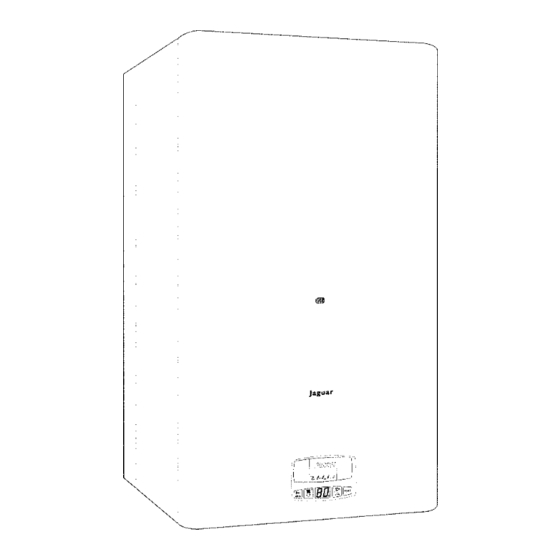
Summary of Contents for Glow-worm Jaguar 23 kW
- Page 1 23 kW wall hung combination boiler 28 kW wall hung combination boiler User, Installation and Servicing Instructions This is a Cat II appliance 2H3+ Manufactured exclusively for Plumb Center by Hepworth Heating Division...
-
Page 2: Table Of Contents
Note: The boiler serial number is marked on the data label attached to the fascia behind the front panel. Refer to the ‘Introduction’ section for a description of the basic functions of the boiler. The ‘User’ section describes how to safely operate the boiler. -
Page 3: Users Instructions
USERS INSTRUCTIONS The Jaguar is a wall mounted combination boiler providing central heating and instanta- neous domestic hot water. These instructions should be carefully followed for the safe and economical use of your boiler. Gas leak or fault If a gas leak or fault exists or is suspected, turn the boiler and gas supply off and consult the local gas company or your Installer/Service provider. - Page 4 Diagram 1 Controls: 1 – mains on/off switch 6 – reset button 2 – system pressure LED 7 – increase button 3 – central heating LED 8 – decrease button 4 – display 9 – pressure/mode button 5 – domestic hot water LED The Bar/Mode button functions press of button –...
- Page 5 Domestic hot water setting • Press Bar/Mode button until LED (5) flashes. • Using buttons (7) and (8) set the desired hot water temperature Setting steps: 40, 42, 45, 48, 50, 52, 55, 58, 60 °C • Set ´– –´ if hot water is not required. •...
-
Page 6: Timeclock Instruction
CLOCK - INSTRUCTIONS FOR USE General Description The timeclock has an internal, factory set pro- gramme which switches the boiler ‘On’ and ‘Off’ three times a day as below. 1st ..ON ..06.30 1st . - Page 7 Note. The boiler will stay ‘On’ or ‘Off’, as selected, until the timeclock programme reaches its next ‘On’ or ‘Off’ time. From then on, the timeclock will switch the boiler ‘On’ and ‘Off’ according to the internal programme. When the boiler is again controlled by the internal programme the ‘On’...
- Page 8 To Check the Programme ‘On’ and ‘Off’ Times The programmed ‘On’ and ‘Off’ times can be checked at any time by moving the slide switch from ‘RUN’ to ‘SET‘. Successive presses of the ‘Enter’ button will then show the ‘On’ and ‘Off’ times. Always return the slide switch to ‘RUN’...
-
Page 9: Draining And Filling
DRAINING AND FILLING CAUTION: The boiler is installed as part of a sealed system which must only be drained and filled by a competent person. If the pressure drops to 0.8 bar the pressure LED on the Bar/MODE button starts to flash. -
Page 10: Installation Instructions
INSTALLATION INSTRUCTIONS INTRODUCTION The Jaguar is a wall mounted combination boiler providing central heating and instanta- neous domestic hot water. The boiler is of the II category for use with Natural gas (G20) as distributed in the 2H3+ United Kingdom, or with Butane or Propane gas (G30/G31) with the appropriate con- version kit. -
Page 11: Technical Data Jaguar 23
JAGUAR 23 – TECHNICAL DATA CE Certification ........n° ............0063BL3573 Class ..........................II 2H3+ Type ..........................C Gas type ................. G20 ....G30 ....G31 Max. / min. Heat Input ......kW ..25.8 / 11.4 ..25.8 / 11.4 ..25.8 / 11.4 Max. -
Page 12: Technical Data Jaguar 28
JAGUAR 28 – TECHNICAL DATA CE Certification ........n° ............0063BL3573 Class ..........................II 2H3+ Type.......................... C Gas type ................. G20 ....G30 ....G31 Max. / min. heat input ......kW ..30.3/13.1 ..30.3/13.1 ..30.3/13.1 Max. / min. heat output ......kW ..27.6/11.0 ..27.6/11.0 ..27.6/11.0 EFFICIENCY (PCI) Nominal efficiency ........ -
Page 13: Dimensions
DIMENSIONS AND PRESSURE AVAILABLE Jaguar 23 Jaguar 28 Diagram 2 1 – Heating flow (pipe diameter 22 mm) 5 – Heating return (pipe diameter 22 mm) 2 – Hot water outlet (pipe diameter 15 mm) 6 – Wall 3 – Gas inlet (pipe diameter 22 mm) 7 –... -
Page 14: Boiler Schematic
BOILER SCHEMATIC 1 – Air pressure switch 16 – DHW outlet 2 – Fan 17 – Automatic by-pass 3 – Heat exchanger 18 – Heating flow 4 – Burner 19 – Drain 5 – Gas valve 20 – Microswitch 6 – Expansion vessel 21 –... -
Page 15: Installation Section
INSTALLATION SECTION Clearances To allow for servicing, the boiler should be installed with the following clearances: 50 mm either side of the boiler 600 mm to the front of the boiler 300 mm below the boiler 200 mm above the boiler TERMINAL POSITION The minimum acceptable spacings from the terminal to obstructions and ventilation openings are shown in diagram 5 below:... -
Page 16: Heating And Hot Water System Design
HEATING SYSTEM DESIGN The Jaguar is compatible with any type of sealed system installation, i.e. radiators, fan convectors etc. Pipe sectional areas shall be determined in accordance with normal practices, using the pump curve, refer to ‘Technical Data’. The distribution system shall be calculated in accordance with the output requirements of the actual system, not the maximum output of the boiler. - Page 17 Safety valve discharge WARNING: It must not discharge above an entrance or window or any type of public access area. Connect the safety valve discharge pipe to the valve, the discharge must be extend- ed using not less than 15 mm o.d. pipe, to discharge in a visible position outside the building, facing downward, preferably over a drain.
- Page 18 BOILER TEMPLATE Jaguar 23 Jaguar 28 Boiler connections A Heating flow B Hot water outlet C Gas connection D Cold water mains inlet E Heating return F Safety valve discharge connection Diagram 7...
-
Page 19: Boiler Installation
BOILER INSTALLATION To install the boiler, proceed as follows: • Allowing sufficient clearances for servicing/repair, place the template on the wall (see diagram 7). Note: The boiler can be installed only on the closed wall. • Determine the position of the flue hole and drill hole for flue, preferably using a 120 mm core drill. - Page 20 • Fit gasket (E) onto underside of flue elbow (D). • Carefully insert ‘O’ ring (J) into upper and lower parts of inner elbow. • Place spacer (K) (supplied with boiler) onto top of boiler Jaguar 23 only (see dia- gram 9).
-
Page 21: Telescopic Horizontal Flue Installation
TELESCOPIC HORIZONTAL FLUE INSTALLATION Telescopic Top Outlet Flue Pack 1/08/705 Flue Position and Length Determine flue application, length and terminal position before starting. Refer to diagram 9a. To make a neat finish to the flue outlet a flue collar is included. Flue Assembly Extend the telescopic flue to the required length, making sure that the minimum over- lap is no less than 15 mm, and that the flue terminal projects 20 mm beyond wall face. -
Page 22: Vertical Flue Installation
VERTICAL FLUE INSTALLATION • Fit gasket (E) onto underside of vertical adaptor (O) – see diagram 10. • Carefully insert ‘O’ ring (J) into vertical adaptor inner spigot. • Place spacer (K) on the top of boiler (Jaguar 23 only). •... -
Page 23: Flue Configurations
FLUE CONFIGURATIONS Diagram 1 1... -
Page 24: Electrical Connection
ELECTRICAL CONNECTION Warning: This boiler must be earthed. All system components must be of an approved type. Connection of the whole electrical system and any heating system controls to the electri- cal supply must be through a common isolator. Isolation should preferably be by a double pole switched fuse spur box having a mini- mum contact separation of 3 mm on each pole. -
Page 25: Commissioning
COMMISSIONING The commissioning and first firing of the boiler must only be carried out by a competent person. To gain access to the inside of the boiler undo screw securing front panel at the boiler bottom, remove front panel by pulling forwards, lifting it up and off. Note – upper edge of front casing is fixed to the boiler by means of 2 pins. - Page 26 • Restart boiler and operate until a maximum temperature is reached. Shut down boiler and vent air from heating system. If necessary, top up heating system and make sure that a pressure at least of 1 bar is indicated on the display when system is COLD. Gas installation It is recommended that any air is purged from the supply at the gas inlet test point on the gas valve, see diagram 13.
- Page 27 Safety devices Air flow rate safety device If an obstruction, even partial, of the flue occurs, the built in safety system of the boiler will turn the boiler OFF. The boiler will be ready to operate when the fault has been cleared.
-
Page 28: Servicing Instructions
SERVICING INSTRUCTIONS To ensure the continued efficient and safe operation of the boiler, it is recommended that it is checked and serviced at regular intervals. The frequency of servicing will depend upon the installation conditions and usage but, in general, once a year should be enough. It is the law that any servicing is carried out by a competent person. -
Page 29: Replacement Of Parts
Cleaning the burner (Jaguar 28) • Unscrew and remove 6 screws securing com- bustion chamber cover and remove cover. • Disconnect flame sense electrode at burner. • Disconnect ignition lead at gas valve module. • Disconnect ignition earth lead. • Undo nuts (A) securing gas supply pipe between burner and gas valve and remove pipe, see di- agram 17b. - Page 30 To replace air pressure switch • Locate air pressure switch in upper left hand corner of sealed chamber. • Pull off clear plastic tube from base of switch. • Remove electrical connections from the switch. Important: Mark the connectors – it is necessary they have to be connected in the same position.
- Page 31 Note: It is not necessary to drain down entire heating circuit to carry out this work. Simplification: for simpler work remove gas valve module and right side cover. • Disconnect pump cable. • Remove 2 clips fixing pump, see diagram 20. •...
- Page 32 To replace heating water thermistor • Locate thermistor (b) clipped onto flow pipe to left hand side of sealed chamber below overheat thermostat, see diagram 21. • Unclip thermistor from pipe. • Pull off electrical connections from thermistor. • Fit replacement thermistor in reverse order to re- moval.
- Page 33 To replace timeclock • Remove PCB cover as described in ‘To replace PCB’ • Disconnect clock electrical connections from PCB. Unclench and remove plastic clips securing timeclock to lower front panel. • Remove control panel sticker and timeclock from panel. •...
-
Page 34: Schematic Wiring Diagram
SCHEMATIC WIRING DIAGRAM Diagram 24... -
Page 35: Fault Finding
FAULT FINDING Before fault finding, make sure that: All gas cocks are open and there is an inlet gas pressure of 20 mbar (G 20) The heating system pressure is at least 1 bar. There is a permanent mains supply to the boiler The fuses on the PCB are intact. - Page 36 F2 Central heating thermistor Check if flow thermistor is not failure disconnected or short-circuited Sensor Ohm resistance 10 kΩ by 25°C, 12,7 kΩ by 20°C, 16 kΩ by 15°C CH water temperature Check if system is not frozen below 3°C F3 Heat exchanger blockage Check main heat exchanger Boiler shuts down and Check domestic heat...
-
Page 37: Conversion To Lpg
JAGUAR – CONVERSION TO LPG Note: Conversion must only be carried out by a competent person • Isolate boiler from the gas and electrical supplies. • Remove boiler casing, sealed chamber and combustion chamber cover as described in Installation/Servicing Instructions. •... - Page 38 • Replace the PCB box and all covers • Stick the self-adhesive label (delivered with LPG conversion kit) bearing the information about the gas type and the gas supply pressure on the visible place inside the boiler. Jaguar 23 Inj. diam. Pmin Pmax G20 (20 mbar)
- Page 39 NOTES:...
- Page 41 Nottingham Road Belper, Derbyshire, DE56 IJT Model: Jaguar Serial No: Output kW: Installation date: ../ .... / ....Installers name/address: ........Installation Engineer: ................................ABOUT YOUR GUARANTEE In order to register the quarantee of your new boiler, complete and send section 1 within 10 days of installation and retain section 2 for future reference.
- Page 42 ✁ Model: Jaguar Serial No: Output kW: THIS CARD TO BE RETURNED WITHIN 10 DAYS OF INSTALLATION USER INSTALLER Name: ..........Installers name / address ......Address: ................................................Postcode: ......................Telephone No........Date: .... / ..../ .....
- Page 43 FREEPOST JAGUAR REGISTRATION DEPARTMENT NOTTINGHAM ROAD BELPER DERBYSHIRE DE56 IJT...
- Page 44 Please do not forget to complete your guarantee registration card.
- Page 45 Supported by: Customer Services: Tel: (01773) 828100 Fax: (01773) 828070 One Contact Local Service 18. October 2001...
- Page 46 GUARANTEE CONDITIONS This appliance is guaranteed for a period of 12 months from the date of commissioning or 18 months from the date of despatch from our warehouse whichever is the shorter and covers manufacturing defects only. The Manufacturer undertakes to repair or replace parts, free of charge, which are recognised by us to be of faulty manufacture, if necessary, after return to our factory for examination, on condition that: The appliance was installed by a qualified gas installer in accordance with installation...
Need help?
Do you have a question about the Jaguar 23 kW and is the answer not in the manual?
Questions and answers