Table of Contents
Advertisement
IMPORTANT MANUAL
OWNER'S MANUAL
MODEL NUMBER:
961980056
SNOW THROWER
Gasoline containing up to 10% ethanol (E10) is acceptable for use in this machine.
The use of any gasoline exceeding 10% ethanol (E10) will void the product warranty.
Always Wear Eye Protection During Operation
581 13 01-27 Rev. 1
Do Not Throw Away
WARNING:
Read the Owner's Manual and
fol low all Warnings and Safety
In struc tions. Fail ure to do so
can result in serious injury.
Advertisement
Table of Contents

Subscribe to Our Youtube Channel
Related Manuals for Poulan Pro 961980056


Summary of Contents for Poulan Pro 961980056
- Page 1 Do Not Throw Away OWNER'S MANUAL MODEL NUMBER: WARNING: Read the Owner's Manual and 961980056 fol low all Warnings and Safety In struc tions. Fail ure to do so can result in serious injury. SNOW THROWER Gasoline containing up to 10% ethanol (E10) is acceptable for use in this machine.
-
Page 2: Safety Rules
IMPORTANT Safe Operation Practices for Walk-Behind Snow Throwers This snow thrower is capable of amputating hands and feet and throwing objects. Failure to observe the following safety instructions could result in serious injury. WARNING: Snow throwers have ex- Look for this symbol to point out im- posed rotating parts, which can cause por tant safety precautions. -
Page 3: Table Of Contents
Clearing a Clogged Discharge Chute 6. When cleaning, repairing or inspecting the snow thrower, stop the engine and make certain the collector/impel- Hand contact with the rotating impeller inside the discharge ler and all moving parts have stopped. Disconnect chute is the most common cause of injury associated with the spark plug wire and keep the wire away from the snow throwers. -
Page 4: Assembly / Pre-Operation
PARTS PACKED SEPARATELY IN CARTON (1) AUGER CONTROL ROD (1) MULTI- WRENCH (180684) (3) RETAINER SPRINGS (2) FLAT WASHERS (169675) (1) POWER CORD (198563) (1) DISCHARGE CHUTE ROTATOR HEAD MOUNTING (2) CARRIAGE BOLTS 3/8-16 x 2.25 SAFTEY IGNITION KEY(S) (443059) (1) WASHER 3/8 (1) LOCKNUT 3/8 (19131316) - Page 5 ASSEMBLY / PRE-OPERATION NOTE: The multi-wrench may be used for assembly of the INSTALL TRACTION DRIVE CONTROL ROD chute rotator head to snow thrower and making ad just ments (See Figs. 3 and 4) to the skid plates. The traction drive control rod is installed on the snow thrower.
- Page 6 ASSEMBLY / PRE-OPERATION INSTALL DISCHARGE CHUTE / CHUTE ROTATER INSTALL AUGER CONTROL ROD (See Figs. 5 and 6) HEAD (See Fig. 7) 1. Retrieve vinyl sleeve and spring from bag of parts and retrieve the auger control rod from carton chute tray. NOTE: The multi-wrench provided in your parts bag may Slide straight rod end through the small hole in the be used to install the chute rotater head.
-
Page 7: Operation
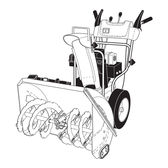
OPERATION KNOW YOUR SNOW THROWER READ THIS OWNER'S MANUAL AND ALL SAFETY RULES BEFORE OPERATING YOUR SNOW THROWER. Compare the illustrations with your snow thrower to familiarize yourself with the location of various controls and adjustments. Save this manual for future reference. These symbols may appear on your snow thrower or in literature supplied with the product. - Page 8 OPERATION MUF FLER ELECTRIC AUGER DISCHARGE CHUTE CONTROL LEVER START CONTROL BUTTON LEVER GAS O LINE TRACTION DRIVE SPEED FILLER CAP DRIVE CON TROL LEVER POWER CONTROL CORD LEVER PLUG CHOKE CHUTE CON- DE FLEC TOR TROL SAFETY IGNITION ON / OFF SWITCH DISCHARGE PRIM ER...
- Page 9 OPERATION The operation of any snow thrower can result TO CONTROL SNOW DISCHARGE (See Figs. 11 & 12) in foreign objects thrown into the eyes, which can result in severe eye damage. Always wear WARNING: Snow throwers have ex- safety glasses or eye shields while operating posed rotating parts, which can cause your snow thrower or performing any ad just- severe injury from contact, or from ma-...
- Page 10 OPERATION TO THROW SNOW (See Fig. 13) TO MOVE FORWARD AND BACKWARD (See Fig. 15) The auger rotation is controlled by the auger control lever SELF-PROPELLING, forward and reverse movement of located on the right side handle. the snow thrower, is controlled by the traction drive control lever located on the left side handle.
- Page 11 OPERATION BEFORE STARTING THE ENGINE NOTE: It is not recommended to operate the snow thrower over gravel or rocky surfaces. Objects such as gravel, rocks CHECK ENGINE OIL LEVEL (See Fig. 18) or other debris, can easily be picked up and thrown by the The engine on your snow thrower has been shipped from impeller, which can cause serious personal injury, property the factory already filled with oil.
- Page 12 OPERATION TO START ENGINE 6. When the engine starts, release the recoil starter han dle and slowly move the choke control to the “OFF” posi- • Be sure fuel shut-off valve is in the “OPEN” position. tion. Your snow thrower engine is equipped with both a 120 Volt Allow the engine to warm up for a few minutes.
-
Page 13: Maintenance Schedule
MAINTENANCE GENERAL REC OM MEN DA TIONS LUBRICATION CHART The warranty on this snow thrower does not cover items that have been sub ject ed to operator abuse or negligence. ➀ SAE 30 Motor Oil To receive full value from the warranty, operator must ➁... - Page 14 MAINTENANCE BELTS TO CHANGE ENGINE OIL Check belts for deterioration and wear after every 50 hours Determine temperature range anticipated before next oil of operation and replace if necessary. The belts are not change. All oil must meet API service classification SG–SL. ad just able.
-
Page 15: Service And Adjustments
SERVICE AND ADJUSTMENTS To replace the capscrew/shear bolts: WARNING: To avoid serious injury, 1. Disengage all controls and move throttle control to before performing any service or ad- STOP position. Wait for all moving parts to stop. just ments: 2. Remove safety ignition key and disconnect spark plug 1. - Page 16 SERVICE AND ADJUSTMENTS TO REPLACE BELTS (See Fig. 21) 8. RELIEVE TENSION ON TRACTION DRIVE BELT IDLER and remove traction drive belt from around The auger and traction drive belts are not adjustable. If pulleys. the belts are damaged or begin to slip from wear, they should be replaced.
- Page 17 SERVICE AND ADJUSTMENTS TO REMOVE WHEELS (See Fig. 22) TO ADJUST TRACTION BELT AND AUGER BELT TENSION • Remove the wheel pin and retainer pin and remove wheel from axle. If the traction or auger belt is slipping because it is not tight enough when engaged, the tension can be increased by IMPORTANT: When installing wheel, be sure to use the in- adjusting the spring location in the control rod.
-
Page 18: Storage
STORAGE Immediately prepare your snow thrower for storage at • Empty the fuel tank by starting the engine and letting it run until the fuel lines and car bu re tor are empty. the end of the season or if the unit will not be used for 30 days or more. -
Page 19: Troubleshooting
TROUBLESHOOTING See appropriate section in manual unless directed to an authorized service center/department. PROBLEM CAUSE CORRECTION Does not start 1. Fuel shut-off valve (if so 1. Turn fuel shut-off valve to OPEN position. equipped) in OFF position. 2. Safety ignition key 2. -
Page 20: Repair Parts
REPAIR PARTS SNOW THROWER - - MODEL NUMBER 961980056 (96198005601) AUGER HOUSING / IMPELLER ASSEMBLY 2 (EXPLODED) 01.07.026-F NOTE: All component dimensions given in U.S. inches. 1 inch = 25.4 mm IMPORTANT: Use only Original Equipment Manufacturer (O.E.M.) replacement parts. - Page 21 REPAIR PARTS SNOW THROWER - - MODEL NUMBER 961980056 (96198005601) AUGER HOUSING / IMPELLER ASSEMBLY PART DESCRIPTION 532 19 41-05 IMPELLER 532 42 71-48 GEARBOX ASSEMBLY 532 18 89-09 BEARING 532 42 71-46 IMPELLER PULLEY 532 44 24-38 DISCHARGE BASE...
- Page 22 REPAIR PARTS SNOW THROWER - - MODEL NUMBER 961980056 (96198005601) AUGER HOUSING / IMPELLER ASSEMBLY PART DESCRIPTION 532 41 52-95 AUGER HOUSING 532 40 78-25 SCRAPER BAR 872 27 05-05 CARRIAGE BOLT 5/16−18 X .625 532 15 53-77 NUT 5/16−18...
- Page 23 REPAIR PARTS SNOW THROWER - - MODEL NUMBER 961980056 (96198005601) AUGER HOUSING / IMPELLER ASSEMBLY PART DESCRIPTION 532 42 04-78 AUGER BEARING 532 41 19-39 BEARING PLUG 532 17 95-82 SCREW 5/16−18 X 1.00 01.07.024-B PART DESCRIPTION 532 43 59-51...
- Page 24 REPAIR PARTS SNOW THROWER - - MODEL NUMBER 961980056 (96198005601) AUGER HOUSING / IMPELLER ASSEMBLY PART DESCRIPTION 532 18 47-47 DRIFT CUTTER BAR 872 27 05-06 CARRIAGE BOLT 5/16−18 X .750 01.16.001-B 532 17 92-46 PLASTIC WASHER 810 04 05-00...
- Page 25 REPAIR PARTS SNOW THROWER - - MODEL NUMBER 961980056 (96198005601) CONTROL PANEL / CHUTE PART DESCRIPTION 532 44 36-24 CHUTE WELDMENT 532 18 45-11 DEFLECTOR WELDMENT 532 42 03-25 DEFLECTOR SEAL 532 18 41-14 STRAP 532 44 50-19 KNOB BLACK...
- Page 26 REPAIR PARTS SNOW THROWER - - MODEL NUMBER 961980056 (96198005601) CONTROL PANEL / CHUTE 01.09.010-B PART DESCRIPTION 532 42 82-72 LEVER/CABLE ROTATOR ASSEMBLY 817 50 10-10 SCREW 10-24 X .625 532 42 06-78 ROTATOR HEAD 532 40 59-32 ROTATOR PIVOT BRACKET...
- Page 27 REPAIR PARTS SNOW THROWER - - MODEL NUMBER 961980056 (96198005601) HANDLES PART DESCRIPTION 532 42 10-69 PLOW HANDLE LH 532 42 10-70 PLOW HANDLE RH 532 42 91-48 PANEL BRACKET LH 532 19 69-43 PANEL BRACKET RH 532 19 95-13...
- Page 28 REPAIR PARTS SNOW THROWER - - MODEL NUMBER 961980056 (96198005601) HANDLES 01.08.002-J PART DESCRIPTION 532 41 55-39 CONTROL PANEL 580 68 78-02 CONTROL LEVER LH 580 68 78-01 CONTROL LEVER RH 532 41 55-46 TRACTION ROD ARM 532 42 90-98...
- Page 29 REPAIR PARTS SNOW THROWER - - MODEL NUMBER 961980056 (96198005601) HANDLES PART DESCRIPTION 580 79 77-01 IMPELLER ROD ASSEMBLY 580 79 79-01 TRACTION ROD ASSEMBLY 532 18 04-45 SHIFTER ROD TOP 532 18 77-16 SHIFTER ROD BOTTOM 532 18 04-47...
- Page 30 REPAIR PARTS SNOW THROWER - - MODEL NUMBER 961980056 (96198005601) HANDLES PART DESCRIPTION 532 18 33-52 CONSOLE PANEL 532 18 44-71 SCREW 10−24 X .625 532 17 52-62 SCREW 10−24 X 1.25 01.10.001-B PART DESCRIPTION 532 41 62-88 INTERLOCK SPRING...
- Page 31 REPAIR PARTS SNOW THROWER - - MODEL NUMBER 961980056 (96198005601) DRIVE 01.03.005-C PART DESCRIPTION 532 18 82-26 (assy of 1a,1b) AXLE ASSEMBLY 532 17 93-52 AXLE SHAFT 532 18 42-06 ROLL PIN 3/16 532 40 26-91 SPROCKET 532 17 46-97...
- Page 32 REPAIR PARTS SNOW THROWER - - MODEL NUMBER 961980056 (96198005601) DRIVE ITEM 42 EXPLODED 01.02.013-C NOTE: All component dimensions given in U.S. inches. 1 inch = 25.4 mm IMPORTANT: Use only Original Equipment Manufacturer (O.E.M.) replacement parts. Failure to do so could be hazardous, damage your snow thrower and void your warranty.
- Page 33 REPAIR PARTS SNOW THROWER - - MODEL NUMBER 961980056 (96198005601) DRIVE PART PART DESCRIPTION DESCRIPTION 532 17 53-44 BEARING 532 19 88-75 SPEED SELECTOR 532 17 86-13 WHEEL HUB ASSEMBLY 874 76 05-14 SCREW 5/16-18-.875 817 50 10-10 SCREW 10-24 X .625...
- Page 34 REPAIR PARTS SNOW THROWER - - MODEL NUMBER 961980056 (96198005601) CHASSIS / ENGINE / PULLEYS PART DESCRIPTION 532 43 60-67 COMPLETE LCT ENGINE PW2HK18650178E 01.00.034-A 532 42 92-75 FRAME 532 15 04-06 BOLT 3/8-16 532 42 88-67 SCREW 5/16-18 X .750...
- Page 35 REPAIR PARTS SNOW THROWER - - MODEL NUMBER 961980056 (96198005601) CHASSIS / ENGINE / PULLEYS 01.21.003-D PART PART DESCRIPTION DESCRIPTION 532 40 80-07 IMPELLER BELT 874 78 05-20 SCREW 5/16-18 X 1 .00 532 41 97-44 TRACTION BELT 532 05 92-89...
- Page 36 REPAIR PARTS SNOW THROWER - - MODEL NUMBER 961980056 (96198005601) WHEELS PART DESCRIPTION 532 43 75-22 WHEEL ASSEMBLY LH 532 43 75-23 WHEEL ASSEMBLY RH 01.06.018-A NOTE: All component dimensions given in U.S. inches. 1 inch = 25.4 mm IMPORTANT: Use only Original Equipment Manufacturer (O.E.M.) replacement parts.
- Page 37 REPAIR PARTS SNOW THROWER - - MODEL NUMBER 961980056 (96198005601) BAG OF PARTS PART DESCRIPTION 532 19 85-63 POWER CORD 532 16 96-75 RETAINER PIN 532 42 91-12 WRENCH 873 80 06-00 LOCKNUT 3/8−16 819 13 13-16 WASHER 3/8 532 19 20-90 SHEAR BOLT 1/4−20 X 1−3/4...
- Page 38 REPAIR PARTS SNOW THROWER - - MODEL NUMBER 961980056 (96198005601) DECALS PART DESCRIPTION 532 18 10-37 DECAL, DANGER 532 18 10-35 DECAL, DANGER, DEFLECTOR 532 18 10-42 DECAL, DANGER 532 18 10-33 DECAL, INSTRUCTION 532 42 95-91 DECAL, CON RT SPD/LEV/PWST...
- Page 39 SERVICE NOTES...
-
Page 40: Warranty
LIMITED WARRANTY The Manufacturer warrants to the original consumer purchaser that this product as manufactured is free from defects in mate- rials and work man ship. For a period of two (2) years from date of purchase by the original consumer purchaser, we will repair or replace, at our option, without charge for parts or labor incurred in replacing parts, any part which we find to be defective due to materials or workmanship.
Need help?
Do you have a question about the 961980056 and is the answer not in the manual?
Questions and answers