Table of Contents
Advertisement
Quick Links
weber
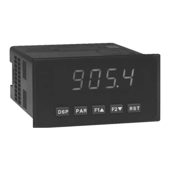
PAX-Panel Meters
MODEL PAX – 1/8 DIN ANALOG INPUT PANEL METERS
GENERAL DESCRIPTION
The PAX Analog Panel Meters offer many features and performance
capabilities to suit a wide range of industrial applications. Available in five
different models to handle various analog inputs, including DC Voltage/Current,
AC Voltage/Current, Process, Temperature, and Strain Gage Inputs. Refer to
pages 4 through 6 for the details on the specific models. The optional plug-in
output cards allow the opportunity to configure the meter for present
applications, while providing easy upgrades for future needs.
The meters employ a bright 0.56" LED display. The unit is available with a
red sunlight readable or a standard green LED. The intensity of display can be
adjusted from dark room applications up to sunlight readable, making it ideal
for viewing in bright light applications.
The meters provide a MAX and MIN reading memory with programmable
capture time. The capture time is used to prevent detection of false max or min
readings which may occur during start-up or unusual process events.
The signal totalizer (integrator) can be used to compute a time-input product.
This can be used to provide a readout of totalized flow, calculate service
intervals of motors or pumps, etc. The totalizer can also accumulate batch
weighing operations.
The meters have four setpoint outputs, implemented on Plug-in option cards.
The Plug-in cards provide dual FORM-C relays (5A), quad FORM-A (3A), or
either quad sinking or quad sourcing open collector logic outputs. The setpoint
alarms can be configured to suit a variety of control and alarm requirements.
Communication and Bus Capabilities are also available as option cards.
These include RS232, RS485, Modbus, DeviceNet, and Profibus-DP. Readout
values and setpoint alarm values can be controlled through the bus.
Additionally, the meters have a feature that allows a remote computer to directly
control the outputs of the meter. With an RS232 or RS485 card installed, it is
possible to configure the meter using a Windows
The configuration data can be saved to a file for later recall.
DIMENSIONS In inches (mm)
weber
S e n s o r s G m b H • S t r o h d e i c h 3 2 • D - 2 5 3 7 7 • K o l l m a r • T e l . : + 4 9 4 1 2 8 - 5 9 1 • info@captor.de
• PROCESS, VOLTAGE, CURRENT, TEMPERATURE, AND STRAIN
GAGE INPUTS
• 5-DIGIT 0.56" RED SUNLIGHT READABLE DISPLAY
• VARIABLE INTENSITY DISPLAY
• 16 POINT SCALING FOR NON-LINEAR PROCESSES
• PROGRAMMABLE FUNCTION KEYS/USER INPUTS
• 9 DIGIT TOTALIZER (INTEGRATOR) WITH BATCHING
• OPTIONAL CUSTOM UNITS OVERLAY W/BACKLIGHT
• FOUR SETPOINT ALARM OUTPUTS (W/OPTION CARD)
• COMMUNICATION AND BUS CAPABILITIES (W/OPTION CARD)
• RETRANSMITTED ANALOG OUTPUT (W/OPTION CARD)
• PC SOFTWARE AVAILABLE FOR METER CONFIGURATION
• NEMA 4X/IP65 SEALED FRONT BEZEL
A linear DC output signal is available as an optional Plug-in card. The card
provides either 20 mA or 10 V signals. The output can be scaled independent of
the input range and can track either the input, totalizer, max or min readings.
Once the meters have been initially configured, the parameter list may be
locked out from further modification in its entirety or only the setpoint values
can be made accessible.
The meters have been specifically designed for harsh industrial environments.
With NEMA 4X/IP65 sealed bezel and extensive testing of noise effects to CE
requirements, the meter provides a tough yet reliable application solution.
SAFETY SUMMARY
All safety related regulations, local codes and instructions that appear in this
literature or on equipment must be observed to ensure personal safety and to
prevent damage to either the instrument or equipment connected to it. If
equipment is used in a manner not specified by the manufacturer, the protection
provided by the equipment may be impaired.
Do not use this unit to directly command motors, valves, or other actuators
not equipped with safeguards. To do so can be potentially harmful to persons or
equipment in the event of a fault to the unit.
®
based program.
Note: Recommended minimum clearance (behind the panel) for mounting clip installation
is 2.1" (53.4) H x 5.0" (127) W.
1
Advertisement
Table of Contents

Subscribe to Our Youtube Channel
Related Manuals for Weber captor PAX Series

Summary of Contents for Weber captor PAX Series
- Page 1 PAX-Panel Meters MODEL PAX – 1/8 DIN ANALOG INPUT PANEL METERS • PROCESS, VOLTAGE, CURRENT, TEMPERATURE, AND STRAIN GAGE INPUTS • 5-DIGIT 0.56" RED SUNLIGHT READABLE DISPLAY • VARIABLE INTENSITY DISPLAY • 16 POINT SCALING FOR NON-LINEAR PROCESSES • PROGRAMMABLE FUNCTION KEYS/USER INPUTS •...
-
Page 2: Table Of Contents
ABLE ONTENTS Ordering Information ....2 Installing the Meter ....8 General Meter Specifications . -
Page 3: General Meter Specifications
ENERAL ETER PECIFICATIONS DISPLAY: 5 digit, 0.56" (14.2 mm) red sunlight readable or standard green 13. CUSTOM LINEARIZATION: LEDs, (-19999 to 99999) Data Point Pairs: Selectable from 2 to 16 Display Range: -19,999 to 99,999 2. POWER: AC Versions: Decimal Point: 0 to 0.0000 AC Power: 85 to 250 VAC, 50/60 Hz, 15 VA PAXT: Ice Point Compensation: user value (0.00 to 650.00 µV/°C) 14. -
Page 4: Universal Dc Input Panel Meter
PAXD - U DC I ODEL NIVERSAL NPUT FOUR VOLTAGE RANGES (300 VDC Max) FIVE CURRENT RANGES (2A DC Max) THREE RESISTANCE RANGES (10K Ohm Max) SELECTABLE 24 V, 2 V, 1.75 mA EXCITATION PAXD SPECIFICATIONS INPUT RANGES: INPUT ACCURACY* ACCURACY* IMPEDANCE/ CONTINUOUS... -
Page 5: Ac True Rms Voltage And Current Meter
PAXH - AC T RMS V ODEL OLT AND URRENT FOUR VOLTAGE RANGES (300 VAC Max) FIVE CURRENT RANGES (5 A Max) ACCEPTS AC OR DC COUPLED INPUTS THREE WAY ISOLATION: POWER, INPUT AND OUTPUTS PAXH SPECIFICATIONS INPUT RANGES: Isolation To Option Card Commons and User Input Commons: 125 Vrms Isolation To AC Power Terminals: 250 Vrms *Conditions for accuracy specification: INPUT... -
Page 6: Thermocouple And Rtd Input Meter
PAXT - T RTD I ODEL HERMOCOUPLE AND NPUT THERMOCOUPLE AND RTD INPUTS CONFORMS TO ITS-90 STANDARDS CUSTOM SCALING FOR NON-STANDARD PROBES TIME-TEMPERATURE INTEGRATOR PAXT SPECIFICATIONS READOUT: Resolution: Variable: 0.1, 0.2, 0.5, or 1, 2, or 5 degrees Scale: F or C RTD INPUTS: Offset Range: -19,999 to 99,999 display units Type: 3 or 4 wire, 2 wire can be compensated for lead wire resistance... -
Page 7: Optional Plug-In Cards
PTIONAL UTPUT ARDS WARNING: Disconnect all power to the unit before SETPOINT CARDS (PAXCDS) installing Plug-in cards. The PAX and MPAX series has 4 available setpoint alarm output plug-in cards. Only one of these cards can be installed at a time. (Logic state of the Adding Option Cards outputs can be reversed in the programming.) These plug-in cards include: The PAX and MPAX series meters can be fitted with up to three optional plug-... -
Page 8: Installing The Meter
1.0 I NSTALLING THE ETER Installation While holding the unit in place, push the panel latch over the rear of the unit so that the tabs of the panel latch engage in the slots on the case. The panel The PAX meets NEMA 4X/IP65 requirements when properly installed. The latch should be engaged in the farthest forward slot possible. - Page 9 PAXP Jumper Selection Main Circuit JUMPER SELECTIONS Board indicates factory setting. USER INPUT JUMPER LOCATION PAXH Jumper Selection CAUTION: To maintain the electrical safety of the meter, remove JUMPER SELECTIONS unneeded jumpers completely from the meter. Do not move the indicates factory setting.
-
Page 10: Wiring The Meter
PAXT Jumper Selection RTD Input Jumper One jumper is used for RTD input ranges. Select the proper range to match the RTD probe being used. It is not necessary to remove this jumper when Main not using RTD probes. Circuit Board JUMPER SELECTIONS indicates factory setting. - Page 11 3.2 INPUT SIGNAL WIRING PAXD INPUT SIGNAL WIRING Before connecting signal wires, the Input Range Jumper and Excitation Jumper should be verified for proper position. Voltage Signal Current Signal Current Signal (2 wire Current Signal (3 wire (self powered) (self powered) requiring excitation) requiring excitation) Terminal 4: -ADC...
- Page 12 PAXH INPUT SIGNAL WIRING Before connecting signal wires, the Signal, Input Range and Couple Jumpers should be verified for proper position. Voltage Signal Current Signal (Amps) Current Signal (Milliamps) CAUTION: Connect only one input signal range to the meter. Hazardous signal levels may be present on unused inputs.
-
Page 13: Reviewing The Front Buttons And Display
3.3 USER INPUT WIRING Before connecting the wires, the User Input Logic Jumper should be verified for proper position. If not using User Inputs, then skip this section. Only the appropriate User Input terminal has to be wired. Sinking Logic Sourcing Logic Terminal 8-10: Terminal 8-10: + VDC thru external switching device... -
Page 14: Programming The Meter
5.0 P ROGRAMMING THE ETER OVERVIEW PROGRAMMING MENU STEP BY STEP PROGRAMMING INSTRUCTIONS: DISPLAY MODE The meter normally operates in the Display Mode. In this mode, the meter displays can be viewed consecutively by pressing the key. The PROGRAMMING MODE ENTRY (PAR KEY) annunciators to the left of the display indicate which display is currently shown;... - Page 15 1-INP 5.1 MODULE 1 - S IGNAL NPUT ARAMETERS PAX PARAMETER MENU PAXT PARAMETER MENU Refer to the appropriate Input Range for the selected PAXS INPUT RANGE rAN6E meter. Use only one Input Range, then proceed to Display RANGE Decimal Point. SELECTION RESOLUTION 0.
- Page 16 DISPLAY ROUNDING* SCALING POINTS* round These bottom selections are not Linear - Scaling Points (2) available for the PAXT. For linear processes, only 2 scaling points are necessary. It is recommended that the 2 scaling points be at opposite ends of the input signal being applied. Rounding selections other than one, cause the Input Display to ‘round’...
- Page 17 4. The maximum scaled Display Value spread between range maximum and DISPLAY VALUE FOR SCALING POINT 2 dSP 2 minimum is limited to 65,535. For example using +20 mA range the -19999 99999 maximum +20 mA can be scaled to is 32,767 with 0 mA being 0 and Display 100.
- Page 18 HOLD DISPLAY RESET MAXIMUM USr-1 rESEt When activated (momentary action), flashes and The shown display is held but all other meter functions continue as long as activated (maintained action). the Maximum resets to the present Input Display value. The d-HLd r-HI Maximum function then continues from that value.
- Page 19 SETPOINT SELECTIONS PRINT REQUEST USr-1 The following selections are accessible only with the Setpoint plug-in card installed. Refer to the Setpoint Card Bulletin shipped with the Setpoint plug-in Print Print card for an explanation of their operation. LISt Select main or alternate setpoints The meter issues a block print through the serial port when activated.
- Page 20 4-SEC 5.4 MODULE 4 - S ECONDARY UNCTION ARAMETERS PARAMETER MENU UNITS LABEL BACKLIGHT* MAX CAPTURE DELAY TIME* HI-t b-LIt 0. 0 3275. 0 sec. 0. 0 When the Input Display is above the present MAX value for the entered The Units Label Kit Accessory contains a sheet of custom unit overlays delay time, the meter will capture that display value as the new MAX reading.
- Page 21 5-tOt 5.5 MODULE 5 - T OTALIZER NTEGRATOR ARAMETERS PARAMETER MENU TOTALIZER HIGH ORDER DISPLAY The totalizer accumulates (integrates) the Input Display value using one of two modes. The first is using a time base. This can be used to compute a time- When the total exceeds 5 digits, the front panel annunciator TOT flashes.
- Page 22 Modules 6, 7, and 8 are accessible only with the appropriate plug-in cards installed. A quick overview of each Module is listed below. Refer to the corresponding plug-in card bulletin for a more detailed explanation of each parameter selection. 6-SPt 5.6 MODULE 6 - S ETPOINT LARM...
-
Page 23: Factory Service Operations
9-FCS 5.9 MODULE 9 - F ACTORY ERVICE PERATIONS PARAMETER MENU DISPLAY INTENSITY LEVEL PAXP - Input Calibration d-LEv Enter the desired Display Intensity Level (0-15) by WARNING: Calibration of this meter requires a signal source with an using the arrow keys. The display will actively dim or accuracy of 0.01% or better and an external meter with an accuracy brighten as the levels are changed. - Page 24 100 OHM RTD Range Calibration AC Couple Offset Calibration - PAXH 1. Set the Input Range Jumper to 100 ohm. CodE 48 r-100 and press PAR. Then choose It is recommended that Input Calibration be performed first. 2. Use the arrow keys to display and press PAR.
-
Page 25: Parameter Value Chart
TROUBLESHOOTING PROBLEM REMEDIES NO DISPLAY CHECK: Power level, power connections CHECK: Active (lock-out) user input PROGRAM LOCKED-OUT ENTER: Security code requested MAX, MIN, TOT LOCKED-OUT CHECK: Module 3 programming CHECK: Module 1 programming, Input Range Jumper position, input connections, input signal level, INCORRECT INPUT DISPLAY VALUE Module 4 Display Offset is zero, press DSP for Input Display PERFORM: Module 9 Calibration (If the above does not correct the problem.) - Page 26 2-FNC 5-tOt User Input and Function Key Parameters Totalizer (Integrator) Parameters FACTORY FACTORY DISPLAY PARAMETER USER SETTING DISPLAY PARAMETER USER SETTING SETTING SETTING dECPt USr-1 * TOTALIZER DECIMAL POINT USER INPUT 1 tbASE USr-2 TOTALIZER TIME BASE USER INPUT 2 1.
-
Page 27: Programming Overview
PAX PROGRAMMING QUICK OVERVIEW... - Page 28 LIMITED WARRANTY The Company warrants the products it manufactures against defects in materials and workmanship for a period limited to one year from the date of shipment, provided the products have been stored, handled, installed, and used under proper conditions. The Company’s liability under this limited warranty shall extend only to the repair or replacement of a defective product, at The Company’s option.
Need help?
Do you have a question about the captor PAX Series and is the answer not in the manual?
Questions and answers