Table of Contents
Advertisement
Quick Links
Advertisement
Table of Contents

Subscribe to Our Youtube Channel
Related Manuals for DEI PVX-4000-2kV-EX


Summary of Contents for DEI PVX-4000-2kV-EX
- Page 1 PVX-4000-2kV-EX Pulsed Voltage Source Operation Manual Directed Energy, Inc. 1609 Oakridge Dr., Suite 100, Fort Collins, CO 80525 (970) 493-1901 sales@ixyscolorado.com www.ixyscolorado.com Manual Document 7650-0024 Rev. A02 © Copyright 2017 IXYS Colorado. All rights reserved. ...
- Page 2 ...
-
Page 3: Table Of Contents
Contents Contents .................................. 3 Safety .................................. 5 Introduction ................................ 6 Description .............................. 6 Front Panel Features ............................. 7 Rear Panel Features ............................ 9 Accessories Included ........................... 10 Operating Considerations ............................ 11 Output Cabling ............................. 11 Pulse Voltages .............................. 11 Trigger Method ............................ 11 Local Operation ............................... 12 Local Mode .............................. 12 Setup ................................ 12 ... - Page 4 Fault Codes .............................. 19 Warranty and Service .............................. 20 Warranty .............................. 20 Factory Service and Support ........................ 21 Declaration of Conformity ............................ 22 ...
-
Page 5: Safety
Opening the cover exposes you to shock and voids the factory warranty. Do not install, handle, or remove the output cables or load while the PVX-4000-2kV-EX is operating. Allow at least 10 minutes after powering down before handling the output cable or load. -
Page 6: Introduction
The PVX-4000-2kV-EX has a pulse generator incorporated into the system. This provides a test system that can be programmed to perform device testing using the front panel LCD controls or a computer interface (RS-232 and USB). -
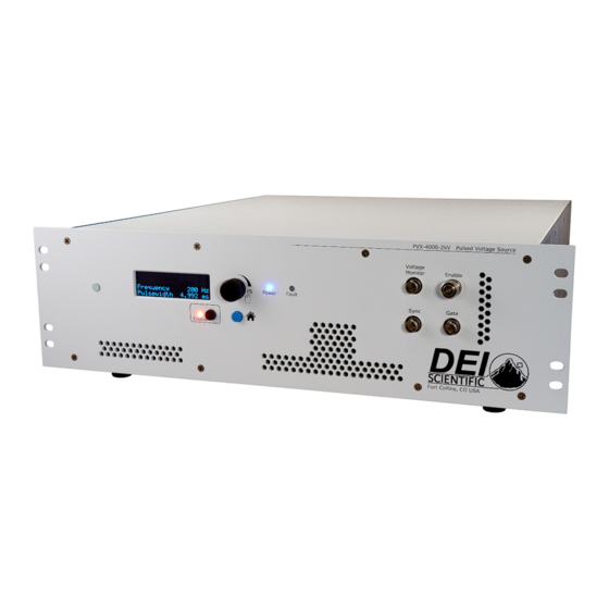
Page 7: Front Panel Features
Front Panel Features Power LED The Power LED is lit when there is support power applied to the PVX-4000-2kV-EX. Fault LED The Fault LED is lit when there is a fault/error sensed within the system. Enable LED... - Page 8 Encoder Knob The encoder changes the values of the displayed parameters. LED Display The display shows system information on the home screen. It is used in conjunction with the encoder. Enable Input The Enable BNC input accepts either an external dry-contact closure or the factory-supplied shorting BNC plug (PCA-9410).
-
Page 9: Rear Panel Features
A Winchester Kings 10 kV, 1065-2 plug is the input connection for the customer-provided negative high voltage power supply. DO NOT TOUCH any part of this input or cable while the PVX-4000-2kV-EX is powered up and enabled. Please review the Safety section. Power Cord Connector The power cord connector accepts a type NEMA C14 grounding equipment power cord. -
Page 10: Accessories Included
The factory-supplied power cord is a type NEMA C14 grounding equipment power cord. Pulsed Output Cable The output cable (PCA-9400) is used to connect the PVX-4000-2kV-EX to the load and is two meters in length. The factory supplied output cable has 1.57 pF / 1.0 cm of cable. This needs to be calculated into the total load value. -
Page 11: Operating Considerations
/ 1.0 cm of cable. This needs to be calculated into the total load value. Pulse Voltages The PVX-4000-2kV-EX pulser is rated at a maximum pulse output voltage of ±2000 V DC. Proper precautions should be taken by the user to ensure that the maximum voltage is not exceeded. -
Page 12: Local Operation
Setup 1. Press the Enable button to disable the voltage output of the system. 2. The PVX-4000-2kV-EX should be OFF for at least ten minutes when connecting or disconnecting the voltage output connector. 3. Connect the customer supplied high voltage power supplies to the positive input and negative input connectors. -
Page 13: Power Up
7. Connect the AC support power cable. Power Up 1. Power up the system with the power switch on the rear panel of the PVX-4000-2kV-EX. The Power LED lights and the Fault LED blinks. The instrument boots up in about 3 seconds. -
Page 14: Set The Pulse Width
When changing the frequency, the duty cycle will be maintained. The system will display the new pulse width as it changes to maintain the duty cycle. It is recommended to change the frequency and then the pulse width, unless the duty cycle has priority to the user. For internal settings: 1. -
Page 15: Power Down
1. If using an external trigger, enable the external signal generator. 2. Enable the External High Voltage Power Supplies. 3. Enable the PVX-4000-2kV-EX unit by pressing the enable button. The green enable LED turns ON. Typically, the user must press the enable button for up to 2 seconds. -
Page 16: Remote Operation
For every command sent to the PVX-4000-2kV-EX, a response will be sent back to the user from the PVX-4000-2kV-EX. The user’s software must wait for a response before sending another command to avoid an overflow of the PVX-4000-2kV-EX receive buffer. -
Page 17: Command List
In the examples, the command or query is in black; the response is in blue italics. *IDN? Abbreviation for identity; returns the manufacturer’s name, unit model number, serial number, firmware revision, and manufacture date. Example: *IDN? DEI Scientific, PVX-4000-2kV-EX, 170151, D01P03, 00 OUTPUT? Returns the state of the output (Enabled or Disabled). Example: OUTPUT? Enabled OUTPUT:ENABLE Enables the output. - Page 18 PULSE:WIDTH? Returns the pulse width of the output pulse in nano-seconds. Example: PULSE:WIDTH? 10,000 ns PULSE:WIDTH nn Sets the pulse width of the output pulse in nano-seconds. Example: PULSE:WIDTH 10000 10,000 ns PULSE:FREQ? Returns the trigger frequency in hertz. Example: PULSE:FREQ? 6000 Hz PULSE:FREQ n...
-
Page 19: Fault Codes
FAULT:CLEAR Fault Codes The following are the fault codes: 0 = no fault code, system ready to be enabled. 1 = enable fault code, the BNC shorting plug is not present. The enable BNC connection is made with less than 1000 Ω (shorted), or use the factory supplied shorting plug. -
Page 20: Warranty And Service
Connected, installed, adjusted, or used otherwise than in accordance with instructions furnished by DEI. DEI reserves the right to make any changes in the design or construction of its products at any time, without incurring any obligation to make any change whatever in units previously delivered. -
Page 21: Factory Service And Support
Factory Service and Support For more information about your instrument or for an operation problem, please contact the factory: Directed Energy, Inc. 1609 Oakridge Dr., Suite 100 Fort Collins, Colorado 80525 (970) 493-1901, ext. 101 sales@ixyscolorado.com techsupport@ixyscolorado.com http://ixyscolorado.com/ Page 21 of 24 For more information contact IXYS Colorado: 970.493.1901 or sales@ixyscolorado.com ... -
Page 22: Declaration Of Conformity
Declaration of Conformity Page 22 of 24 For more information contact IXYS Colorado: 970.493.1901 or sales@ixyscolorado.com Document #7650‐0024 Rev A02. © Copyright 2017 IXYS Colorado. All rights reserved. - Page 23 ...
- Page 24 ...
Need help?
Do you have a question about the PVX-4000-2kV-EX and is the answer not in the manual?
Questions and answers