
Related Manuals for eove EOVE-70


Summary of Contents for eove EOVE-70
- Page 1 EOVE–70 SECRETION MANAGEMENT DEVICE TECHNICAL MANUAL EO-Display version 102-035 Rev DG _ 13/09/2022 _ Apply from API39 Version...
- Page 2 Current version: API39 PAGES CHANGES AND MODIFICATIONS Update of preventive maintenance schedule – Pump must be replaced when the counter 71 / 79 reaches 1000h 83-84 Preventive maintenance alarms...
-
Page 3: Table Of Contents
Structure and operation ......................15 2.3.1 EOVE-70 SMD module structure ................... 15 2.3.2 EO-Display housing unit structure ................. 16 2.3.3 Operation of EOVE-70 SMD module ................17 EOVE-70 Interface ......................... 22 Main menu ..........................22 Preferences ..........................24 Maintenance menu ....................... 25 3.3.1 Maintenance menu interface .................. - Page 4 Software update ........................58 Serial numbers management ....................62 Counters management ......................65 Conditions and procedures of the EOVE-70 maintenance ............68 Preventive maintenance requirements ................. 68 Repair requirements in case of EO-70 SMD failure ............... 68 Cleaning and disinfection ......................68 Surface disinfection .......................
- Page 5 11.3.3 Common SMD failure ....................86 EO-70 SMD module: Replacement procedures ................. 87 12.1 List of components ........................ 87 12.1.1 EOVE-70 SMD module structure ................... 87 12.2 Air Filter ..........................88 12.3 Battery ........................... 89 12.4 Module disassembly ......................90 12.4.1...
- Page 6 12.17 Keyboard.......................... 110 Performances controls via EO-Toolkit ..................110 13.1 Materials requirement ......................110 13.2 Performance controls ......................111 13.2.1 EO-Toolkit Configuration ..................... 112 13.2.2 Generate a snapshot ....................114 13.2.3 Update software versions ................... 115 13.2.4 Test of the LEDs and the keyboard ................116 13.2.5 Electrical interfaces and communication ..............
- Page 7 17.1.3 EO-Display CPU Board electrical connections ............. 142 17.1.4 Electronic boards removal ................... 143 17.1.1 EO-Display CPU board assembly ................. 146 17.1.2 EO-Display handle removal ..................147 17.1.3 EO-Display screen connections ................... 148 17.1.4 Cooling fan removal..................... 150 17.1.5 EO-Display keyboard replacement ................151 17.2 EO-Display assembly ......................
- Page 8 20.2 Battery Fail........................... 170 20.3 Turbine Fail .......................... 171 20.4 Speed Fault .......................... 172 20.5 Sensors failure / CPU Fail / Memory Fail / Device information lost ........173 20.6 Insp. Flow Fail ........................174 20.7 Keyboard Fail ........................175 20.8 No communication between the unit and the ventilator ...........
- Page 9 INTRODUCTION...
-
Page 10: Warnings
1 Warnings Warnings and safety rules This manual is specific to the EOVE-70 (ref EO70) Secretion Management Device (SMD). It provides information for maintenance technicians and operators. Anyone who installs or conducts maintenance operations on the device must be qualified and trained and must have read and understood the entire manual before beginning any operations. -
Page 11: General Information
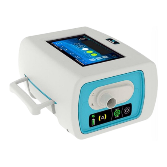
Technical Manual – EOVE-70 MANAGEMENT 2 General information The EOVE 70 (ref EO70) Secretion Management Device (SMD) provides treatment for patients not able to manage their secretions on their own. It provides Insufflation – Exsufflation mode for adults and pediatric patients as prescribed by an attending doctor. - Page 12 Technical Manual – EOVE-70 MANAGEMENT 1. Air inlet/outlet filters cover 2. SpO2 plug 3. DC Power plug 4. Remote control plug Standby button 6. USB port 1 7. USB port 2 REAR VIEW OF DEVICE WITHOUT DOCKING STATION 1. USB port 2.
- Page 13 Technical Manual – EOVE-70 MANAGEMENT VIEW FROM BELOW OF EOVE-70 SMD MODULE 1. Module label with serial number 2. Battery flap KEYBOARD 1. Power source indicator 2. Alarm indicators 3. Treatment start / stop button 4. Power on/off button 5. Battery level indicator...
- Page 14 EO-DISPLAY HOUSING UNIT The EO-Display housing permits to control the EOVE-70 SMD module when it is inserted inside. The screen of the unit displays various information from the EOVE-70 SMD module and enables to set the different parameters. EO-Display housing unit – Inputs and outputs 1.
-
Page 15: The Technical Data
Technical Manual – EOVE-70 MANAGEMENT The Technical data For technical data, refer to the EOVE-70 user guide. Structure and operation 2.3.1 EOVE-70 SMD module structure Pneumatic subassembly Electrical subassembly EOVE-70 SMD module architecture... -
Page 16: Eo-Display Housing Unit Structure
Technical Manual – EOVE-70 MANAGEMENT 2.3.2 EO-Display housing unit structure EO-Display Housing unit architecture 1. Upper shell & display screen 6. Lower shell 2. Cooling fan 7. Covers 3. EO-Display CPU board 8. Connection board & DC plug cable 4. USB board 9. -
Page 17: Operation Of Eove-70 Smd Module
NOTE: When the EOVE-70 SMD is switched on but the ventilation is off, the turbine stills operate to remain cool. There are two speeds for cooling during standby. Below 45°C the turbine speed is low, and above the temperature threshold, the speed is higher. - Page 18 Technical Manual – EOVE-70 MANAGEMENT Operation of EOVE-70 SMD during inspiratory phase During inspiratory phase, the EOVE-70 secretion management device provides positive pressure to the patient. This pressure value depends on the set point configurated by the user and is proportional to the turbine speed.
- Page 19 Operation of EOVE-70 SMD during expiratory phase During the expiratory phase, the EOVE-70 secretion management device creates a suction to assist the patient when he coughs. The air flows through the inspiratory flow sensor, the valve 4, then the turbine and is exhaled by the valve 2.
- Page 20 Technical Manual – EOVE-70 MANAGEMENT The pump still provides additional pressure to the two solenoid valves to control the four valves. However, during the expiratory phase, the solenoid valve B turns on to close the valve 1 and the valve...
- Page 21 Technical Manual – EOVE-70 MANAGEMENT EOVE-70 MANAGEMENT...
-
Page 22: Eove-70 Interface
Technical Manual 3 EOVE-70 Interface Main menu The home screen displays various information about current settings, pressure of treatment, power supply mode, etc... It is reachable from all other menus by pressing Home screen 1. Main menu access 2. Presets configurated 3. - Page 23 Technical Manual NOTE: Clinical settings and maintenance menu access are locked by default. To unlock both menus, reach the main menu and press on unlock button, then validate. To reach the main menu, click on from the home screen Hold unlock button until the validation popup appears Main menu Validate...
-
Page 24: Preferences
Preferences Preferences menu enables to set up different parameters and to access to some information about the EOVE-70 SMD and its interface. From the main menu, click on Preferences From this menu, the user can adjust the following settings of the device. -
Page 25: Maintenance Menu
Technical Manual Or display some information about tablet status or software versions. Maintenance menu 3.3.1 Maintenance menu interface... - Page 26 Technical Manual To access to the maintenance menu, a pin code is required. PIN CODE FOR ALL DEVICES: 6666 WARNING: DO NOT GIVE THE PIN CODE TO THE PATIENT. The Maintenance menu is split in three tabs: “General” tab: Accessories control Language selection Connectivity Interface app and Operating system versions management...
- Page 27 Technical Manual - Display of various counters (battery ageing – turbine – solenoid valve – machine – patient) “Information” tab: - Display of serial number - Display of the current software versions - Display of the operating system information...
-
Page 28: Eove-70 Interface Servicing
Technical Manual EOVE-70 interface servicing 3.4.1 Interface software update WARNING : THE FOLLOWING PROCEDURE ONLY CONCERN THE INSTALLATION OF THE CLINICAL APP ON THE EO-DISPLAY HOUSING UNIT. NOTE: Interface update of the EO-Display must not be done while ventilation module is operating. - Page 29 Technical Manual Click on EO70 user interface Check module autonomy and plug the AC if necessary Click on Continue...
- Page 30 Technical Manual Click on Find Update Verify the version available matches with the one required and click on Install...
- Page 31 Technical Manual Wait for the installation until tablet reboot is complete Check in PREFERENCES menu that the interface version installed is the one required...
-
Page 32: Api Version Change
Technical Manual 3.4.2 API version change The device can operate only if the CPU software and the interface are in same API version. In case of API version change, update all the software in the following order: - Upgrade of the CPU software, - Upgrade of the interface software. -
Page 33: Android System Update
Technical Manual 3.4.3 Android system update Copy the OS version on a USB flash driver with same specifications as those required for the interface update WARNING: Keep OS version and its manifest together and copy them on the USB Drive. Do not modify the manifest which is dedicated to one single version of the OS. - Page 34 Technical Manual Follow update recommendations and press Continue Click on Find Update...
- Page 35 Technical Manual Check that the version displayed is the one required and click on it to launch the update Wait until the installation is complete and the display screen reboots Verify in PREFERENCES menu the Operating System version...
-
Page 36: Help Interface And User Manual Update
Technical Manual 3.4.4 Help interface and user manual update NOTE: The user manual must be updated in the language selected in the interface Download the user manual version in the language required Copy it onto a USB stick Go to the maintenance menu and launch the update of the user manual... - Page 37 Technical Manual Click on “Find Update” Select the file required and click on “Update”...
- Page 38 Technical Manual Wait until the end of the update Activate the Help interface...
- Page 39 Technical Manual Check that the Help shortcut is displayed and click on it Look for the information required...
-
Page 40: Language Selection
Technical Manual 3.4.5 Language selection Current language Language settings... - Page 41 Technical Manual Add a language then slide it up to the top Click on return button, the application will restart automatically. NOTE: The default language is English.
-
Page 42: Brightness Of The Screen
Technical Manual 3.4.6 Brightness of the screen Go to Preferences menu Slide the cursor to adapt the brightness 3.4.7 Transition Beep Go to Preferences menu Enable transitions beep to allow module to always trigger a beep when a transition between inspiration and expiration occurs. -
Page 43: Clear Patient Data
Technical Manual Clear patient data To reset patient data, click on Clear, then Validate WARNING: A CLEAR PATIENT DATA RESETS PATIENT COUNTER AND ERASES ALL THE EVENTS FROM THE SMD MODULE MEMORY. IT RETURNS THE DEVICE TO FACTORY CONFIGURATION. -
Page 44: Smd Management
Physical connection between EO-70 SMD module and its EO-Display housing unit is carried out by the connection board, so, while the module is inserted into the housing unit. To connect the display screen to the EOVE-70 SMD module, insert the module into the EO- Display housing unit and switch it on. - Page 45 Technical Manual Check that the module is connected, and information are displayed on the screen NOTE: API version must match between interface software version and the CPU software version of the ventilation module. Otherwise, a popup appears, and communication fails.
- Page 46 Technical Manual WARNING: EO-Display housing unit dedicated to EO-70 SMD use is not compatible with another ventilation module type such as EO-150 ventilator.
-
Page 47: Calibration
Technical Manual 5 Calibration The patient circuit must be calibrated to provide performances in accordance with EOVE70 SMD specifications. The process detailed below includes two steps which corresponds to the IPPB mode. If the INEX mode is selected, only the first step will be performed. Select the mode required and connect the proper circuit and accessories (without patient interface) Go to the calibration menu... - Page 48 Technical Manual Launch calibration by pressing “Start” Unseal the patient circuit extremity and click on the blinking circle Wait until the circle is complete Seal the patient circuit extremity and click on the blinking circle Wait until the circle is complete Reset the calibration menu by pressing on “Validate”...
- Page 49 Technical Manual Calibration can be aborted at any moment if necessary (by pressing on “abort”, starting the treatment, or selecting another menu) and data collected during the calibration in progress won’t be saved. In case of error during the seal or unseal phases, an error informing about the error will be displayed (image below shows an example during Seal step): Then click on “abort”...
-
Page 50: Eove-70 Smd Servicing
Technical Manual 6 EOVE-70 SMD Servicing EO-Toolkit presentation & settings EO-Toolkit is a servicing software which enables to: Download the event logs Update module software versions Manage the counters and serial numbers Configuration of EO-TOOLKIT Configuration of EO-Toolkit Launch EO-Toolkit... -
Page 51: Events Log Menu / Data Retrieval
6.2.1 Events log The EO-Toolkit log permits to retrieve EOVE-70 SMD technical data until 10 000 events. Thanks to the Auto refresh feature, it is also possible to display the events in live. First connect the device to the computer and launch EO-Toolkit... -
Page 52: Export Clinical Data From Eo-Display
Technical Manual Click on LOG to display the events 1. Refresh 2. Clean the current log 3. Export the current log in an Excel file 4. Auto refresh 5. Generate the event log 6. Filters 6.2.2 Export Clinical data from EO-Display Observance until one year of use can be downloaded and displayed in Clinical Software •... - Page 53 Technical Manual • Go to “Export Data” menu • Generate a new file if necessary, then click on Export to USB...
- Page 54 Technical Manual • Click on Validate • Wait until the export is complete...
-
Page 55: Download Clinical Data From Eo-Toolkit
Technical Manual 6.2.3 Download Clinical data from EO-Toolkit Launch EO-Toolkit and connect the EO-70 SMD module to the computer by USB Click on settings Select the folder where you want to save data then click on OK Click on Connect... -
Page 56: Display The Observance
Technical Manual Click on the dropdown menu Click on create EOZ. Display the observance Launch Clinical Software (from v1.5.0) - Page 57 Technical Manual Import a file and select the appropriate patient. Possibility to add a new patient if necessary (refer to user manual) Display the observance...
-
Page 58: Software Update
WARNING: WINDOWS 10 IS RECOMMENDED. WARNING : MAKE SURE TO CONNECT THE VENTILATOR TO A PORT WHOSE NUMBER IS LESS THAN 10 Launch EO-Toolkit software Connect the EOVE-70 module to AC power Connect the EOVE-70 module to the computer by usb... - Page 59 Technical Manual Click on Settings Go to "Firmwares" tab Select the software package required for the update. NOTE: The package files include the ventilator software (CPU) and power software (PIC) The CPU software file is always named C07000XXX_apiXX.H86 File extension Ventilator API version name...
- Page 60 Technical Manual To update CPU and PIC, click on “Update firmwares” Connect the module to the computer by usb Connect the AC power to the ventilation module Switch off the device then click on OK...
- Page 61 Technical Manual Checking Once the update performed: Pair the EOVE-70 module to the docking station Go to Information tab of Maintenance menu or go to Preferences menu to check that the software versions are updated and displayed properly.
-
Page 62: Serial Numbers Management
NOTE: If the motherboard is changed, it’s necessary to read all the serial numbers and update them in the new board. Launch EO-Toolkit Connect the EOVE-70 module to the computer by usb Click on “Connect” Click on the dropdown menu to display device information... - Page 63 Technical Manual Click on “Serials”...
- Page 64 Technical Manual Change the serial number required for the update and click on ok Check in Information tab of Maintenance menu that the serial number changed is properly updated...
-
Page 65: Counters Management
Operating time of critical components concerned by preventive maintenance must be updated in the Counters tab after a replacement. Launch EO-Toolkit Connect the EOVE-70 module to the computer by usb Click on “Connect” Click on the dropdown menu to display device information... - Page 66 Technical Manual Check in Counters tab of Maintenance menu that the value is correctly updated...
- Page 67 Technical Manual MAINTENANCE OPERATIONS...
-
Page 68: Conditions And Procedures Of The Eove-70 Maintenance
Repair requirements in case of EO-70 SMD failure In case of failure the device must be returned to the technical service, authorised, and certified by EOVE, to perform the troubleshooting and replace the defective components according to the component replacement procedures. -
Page 69: Keredusy Disinfection
Moreover, it limits the risk of contamination while the technical staff repairs or maintains the ventilator. Keredusy can only be used on EO-70 SMD after a request of authorization given by EOVE sales department. Furthermore, a maximum number of 5 disinfections can be performed on the EO70SMD. -
Page 70: Periodical Controls
• Check the status condition of the battery. Replace it if there is any sign of impacts or damage. • Make the EOVE-70 SMD operate on battery mode and AC power source. Full charge the battery if necessary • Check the software versions and update them if necessary... -
Page 71: Preventive Maintenance Operations
Technical Manual – EOVE-70 MAINTENANCE OPERATIONS 10 Preventive maintenance operations The EOVE-70 should be regularly serviced by an authorized EOVE technician according to the following schedule. The SMD device will provide safe and reliable functioning for 10 years provided that it is operated and maintained in accordance with the instructions given in this manual. -
Page 72: Years Maintenance Operation
Technical Manual – EOVE-70 MAINTENANCE OPERATIONS 10.2.2 2 years maintenance operation Replacement of internal filter and the 4 valves OPTIONAL: Replacement of the tubes and sealing rings (depending on device operating time, cleanliness of tubes which must not be becoming yellow, number of disinfections performed). -
Page 73: Control The Pneumatic Sealing Of The Patient Circuit Port
Technical Manual – EOVE-70 MAINTENANCE OPERATIONS 10.3.1 Control the pneumatic sealing of the patient circuit port • Without any port plugged, apply a pressure on the tube 1. • Check that the pressure drops Tube 1 • Plug the various ports with Sealing Test Plugs (SP-SEALPLUG-001) and apply a pressure of 100mbar •... -
Page 74: Inhalation & Exhalation Valves
10.4 Battery 10.4.1 Internal battery information EOVE-70 SDM which reach a storage period exceeding six months could have undergone degradation on internal battery. That is why we hardly recommend to fully charging the module at least every six months during a period of inactivity. - Page 75 WARNING: Spare parts batteries must only be provided by EOVE. Batteries supplied as spare parts are shipped with a charge of 30%. They can be stored for 6 months if they are not connected.
-
Page 76: Configuration Of The New Battery
Technical Manual – EOVE-70 MAINTENANCE OPERATIONS 10.4.2 Configuration of the new battery NOTE: The following operations detail the steps of the internal battery replacement. WARNING: According to the S/N and the battery model, EO-Toolkit wizard performs the recovery or programming of the appropriate battery gauge. - Page 77 Technical Manual – EOVE-70 MAINTENANCE OPERATIONS Select the battery model NOTE: The 2 batteries models have their own references. Refer to the Appendix 4: Spare Parts List to get the references. Enter the new serial number of the battery and click on Next...
- Page 78 Technical Manual – EOVE-70 MAINTENANCE OPERATIONS Click on Next During the next step, the wizard proceeds to the “configuring battery” NOTE: During this operation, the battery gauge configuration is performed, and the battery ageing resets. NOTE: A notification appears when the battery gauge update is successful.
-
Page 79: Pump
Technical Manual – EOVE-70 MAINTENANCE OPERATIONS 10.5 Pump The lifetime of the pump is 1000 hours and an alarm triggers when this duration is reached. The pump counter is available in the "Counters" tab of Maintenance menu. 10.6 Turbine The lifetime of the turbine is 20 000 hours and an alarm triggers when this duration is reached. -
Page 80: Inspiratory Flow Sensor
Technical Manual – EOVE-70 MAINTENANCE OPERATIONS 10.8 Inspiratory flow sensor The inspiratory flow sensor can be replaced after 4 years of operating time depending on sensor conditions (dust, offset, water traces). We recommend checking cleanliness of its external filters and the accuracy of the measure by performing the 2-year maintenance operation with device performance controls. -
Page 81: Curative Maintenance
An alarm, lights on the keyboard and a warning message on the display screen warns the patient when there is a technical problem. The user must immediately contact a technician certified by EOVE and the repair should be performed as soon as possible. -
Page 82: Alarms Conditions
Technical Manual – EOVE-70 MAINTENANCE OPERATIONS 11.1.2 Alarms conditions Alarm Condition / Cause Action Speed Fault Check CPU software version Speed < 1000 rpm Check the connection between the blower board and the during ventilation motherboard Check the inspiratory flow sensor conditions Control vent. - Page 83 Technical Manual – EOVE-70 MAINTENANCE OPERATIONS Turbine Fail Blower temperature Check CPU software version range or Return the device to technical service temperature Open SMD and check pneumatic block sealing accordance with speed Check that there is no leak on internal tubes...
-
Page 84: Eo-Toolkit Event Log
Technical Manual – EOVE-70 MAINTENANCE OPERATIONS Turbine Turbine counter > Replacement of turbine during preventive maintenance Maintenance 20 000 hours Valve Valve counter > Replacement of exhalation control valve during Maintenance preventive maintenance 100 millions cycles Pump Pump counter >... - Page 85 Technical Manual – EOVE-70 MAINTENANCE OPERATIONS Check the alarm didn’t trigger during some tests or is not an old alarm remaining in the event Check the alarm reason is in accordance with device failure or the failure can be reproduced...
-
Page 86: Common Smd Failure
Technical Manual – EOVE-70 MAINTENANCE OPERATIONS 11.3.3 Common SMD failure Regarding EOVE-70 SMD operation, some failure associated to critical components such as the turbine, the motherboard or the battery must trigger alarms, but some breakdowns might not. These breakdowns can cause an unexpected noise or degrade SMD performances. This is a low priority incident but when the user notes something wrong about device operation, it is recommended to return it to technical service to be controlled and fixed if necessary. -
Page 87: Smd Module: Replacement Procedures
WARNING: AFTER REPLACING A COMPONENT, YOU SHOULD FILL THE NEW SERIAL NUMBER IN THE SMD MEMORY. To ensure the proper functioning of the eove-70 secretion management device and the safety of the user and their entourage, the procedures described below must be strictly applied. -
Page 88: Air Filter
Technical Manual – EOVE-70 MAINTENANCE OPERATIONS 12.2 Air Filter Unscrew the cover and remove it Disconnect the two tubes from the inhalation/exhalation valves Remove the two old filters and replace them by new ones Connect back the tubes WARNING: Pay attention to connect the correct tube on the right position... -
Page 89: Battery
NOTE: The new battery must charge for 5 hours before use. Check the condition of protective foams and replace if necessary. NOTE: The EO70 SMD can be equipped by the battery model EOVE 001 (SP- INTBATT-001, yellow) or the battery model EOVE3 (SP-INTBATT-002, black) depending on the manufacturing batch. -
Page 90: Module Disassembly
NOTE: After a discharge, we recommend to fully charge the battery before storing the device. Even if the device must be serviced, that will save the battery life. NOTE: Keep the original EOVE-70SMD screw. Pay attention to not exchange it with the one from EOVE- 150VNT which is different. -
Page 91: Pneumatic Subassembly
Technical Manual – EOVE-70 MAINTENANCE OPERATIONS 12.5 Pneumatic subassembly Some maintenance operations require the removal and installation of the tubes. Be sure to strictly observe the installation and removal instructions of the various components by referring to the following instructions. -
Page 92: Patient Circuit Port
Technical Manual – EOVE-70 MAINTENANCE OPERATIONS 12.5.3 Patient circuit port 12.5.4 Pump... -
Page 93: Inhalation/Exhalation Valves Block
Technical Manual – EOVE-70 MAINTENANCE OPERATIONS 12.5.5 Inhalation/exhalation valves block 12.5.6 Motherboard From patient circuit port Proximal pressure sensor... -
Page 94: Pneumatic Connections
Technical Manual – EOVE-70 MAINTENANCE OPERATIONS 12.6 Pneumatic connections Proximal pressure sensor Exhalation valve Pneumatic Block Turbine Inspiratory flow sensor Pump Inhalation valve Référence Colour Designation Size Silicone tube Ø 3x6mm 145mm Curved tube of turbine output 3 connect. points Silicone tube Ø... -
Page 95: Left View Of Pneumatic Block Assembled
Technical Manual – EOVE-70 MAINTENANCE OPERATIONS 12.6.1 Left view of pneumatic block assembled 12.6.2 Right view of pneumatic block assembled Pneumatic connections between: 1. Solenoid valve A and exhalation valve 2. Pneumatic block and exhalation valve 3. Solenoid valve B and inhalation valve 4. -
Page 96: Electrical Wiring
Technical Manual – EOVE-70 MAINTENANCE OPERATIONS 12.7 Electrical wiring Some maintenance operations require the removal and installation of the cable harnesses. Be sure to strictly observe the installation and removal instructions of the various components by referring to the following instructions. -
Page 97: Internal Pneumatic Circuit
Technical Manual – EOVE-70 MAINTENANCE OPERATIONS 12.8 Internal pneumatic circuit The internal pneumatic circuit is composed of the turbine, the inspiratory flow sensor, the pneumatic block with the two solenoid valves, the inhalation exhalation valves block and all the tubes. - Page 98 Technical Manual – EOVE-70 MAINTENANCE OPERATIONS To remove the internal pneumatic circuit: Disconnect all the cable harnesses from the motherboard Disconnect the turbine from the turbine board the and the tube from the proximal pressure sensor on the motherboard...
-
Page 99: Pneumatic Block
Technical Manual – EOVE-70 MAINTENANCE OPERATIONS 12.9 Pneumatic block Remove the internal pneumatic circuit Disconnect all the six tubes from the pneumatic block Remove the turbine and the inspiratory flow sensor Unscrew the two solenoid valves and remove them Replace the pneumatic block and note the serial number Serial number Connection of the smaller tube. - Page 100 Technical Manual – EOVE-70 MAINTENANCE OPERATIONS Connect the inspiratory flow sensor and pay attention to put it in the proper direction (arrow toward patient circuit port) Connect the turbine and the 6 tubes (pay attention to the two tubes connected to...
-
Page 101: Turbine
Disconnect the turbine board from the motherboard Serial number NOTE: Turbine board serial number is written on the label affixed on the front face NOTE: Keep the original EOVE-70SMD screw. Pay attention to not exchange it with the one from EOVE- 150VNT which is different. -
Page 102: Inhalation / Exhalation Valves
Technical Manual – EOVE-70 MAINTENANCE OPERATIONS 12.12 Inhalation / exhalation valves 12.12.1 Inhalation / exhalation valves installed in pneumatic block Unscrew the two covers on the top of the pneumatic block thanks to the dedicated tool and remove them Remove the valve support with its two sealing rings thanks to the dedicated tool, and the valve for each hole •... -
Page 103: Inhalation / Exhalation Valves Installed In Valves Block
Technical Manual – EOVE-70 MAINTENANCE OPERATIONS 12.12.2 Inhalation / exhalation valves installed in valves block NOTE: Replacement of inhalation and exhalation valves at the rear of the device can be performed with or without a module opening. Module already open... -
Page 104: Solenoid Valves
Technical Manual – EOVE-70 MAINTENANCE OPERATIONS 12.13 Solenoid valves NOTE: We recommend replacing both solenoid valves if the replacement of one of them is required. Solenoid valve A Solenoid valve B 2 ways electrical connector 3 ways electrical connector Solenoid valve... -
Page 105: Pump
Technical Manual – EOVE-70 MAINTENANCE OPERATIONS 12.14 Pump Disconnect the electrical harness from the motherboard Disconnect the tube from the pneumatic block Remove the pump from its slot Note the serial number of the new pump Serial number Connect the two tubes (refer to the image below) 1. - Page 106 Technical Manual – EOVE-70 MAINTENANCE OPERATIONS Connect the electrical harness on the motherboard (refer to electrical wiring $10.7) Pneumatic block Connect the tube of the outlet (backflow) to the pneumatic block NOTE: Position the two tubes so that block them in the shell groove...
-
Page 107: Inspiratory Flow Sensor
Technical Manual – EOVE-70 MAINTENANCE OPERATIONS 12.15 Inspiratory flow sensor Disconnect the electrical harness from the motherboard Disconnect the inspiratory flow sensor from the patient circuit port Disconnect the inspiratory flow sensor from the pneumatic block Top view Note the serial number of the new sensor... -
Page 108: Motherboard
Technical Manual – EOVE-70 MAINTENANCE OPERATIONS 12.16 Motherboard Remove the internal pneumatic circuit and the turbine board then disconnect the pump, the SpO2 and remote-control harnesses from the motherboard Disconnect the keyboard and remove the two turbine feet and the three screws Remove the insulating washer and the nut from DC connector Gently lift (A) the motherboard on the left side then pull it to the left (B). - Page 109 Technical Manual – EOVE-70 MAINTENANCE OPERATIONS Serial number 1. Turbine feet 2. SpO2 connector 3. Remote control connector 4. Keyboard harnesses 5. Screws 6. Insulating washer 7. Nut 8. Washer 9. Lock washer 10. Docking station connection board...
-
Page 110: Keyboard
Stick the new keyboard on the lower shell Connect it to the motherboard 13 Performances controls via EO-Toolkit 13.1 Materials requirement To perform an EOVE-70 SMD final controls, use the materials in the following list or equivalent. MATERIAL PROVIDER REFERENCE... -
Page 111: Performance Controls
Technical Manual – EOVE-70 MAINTENANCE OPERATIONS WARNING: This chapter details how to run an automatic test via EO-Toolkit. Nevertheless, the following list of controls is non-exhaustive. Refer to the instructions listed in the popups which appear during the test. All the tests must pass to consider the device in accordance with specifications. -
Page 112: Eo-Toolkit Configuration
Technical Manual – EOVE-70 MAINTENANCE OPERATIONS 13.2.1 EO-Toolkit Configuration NOTE: Full installation process is detailed in appendix 2. • Launch the EO Toolkit • Click on settings • Configurate/check the different settings before beginning a new performance control 1- Technician... - Page 113 Technical Manual – EOVE-70 MAINTENANCE OPERATIONS • Select the software package required • Click on OK to save the configuration • Select Module Check • Choose the performance control required then click on START CHECK • Select the test and click on start...
-
Page 114: Generate A Snapshot
Technical Manual – EOVE-70 MAINTENANCE OPERATIONS NOTE: If the full performance controls is required, start from the first test “generate module snapshot”. If only ventilation performance controls are expected, start the test from “Security and Blower performances”. It is possible to play a unique test by clicking on Start Single Activity WARNING: After a maintenance operation, full performance controls are necessary. -
Page 115: Update Software Versions
Technical Manual – EOVE-70 MAINTENANCE OPERATIONS This test can be played alone when the device is returned for servicing and a save is necessary before performing any operation. 13.2.3 Update software versions • Connect the module to the external power source •... -
Page 116: Test Of The Leds And The Keyboard
Technical Manual – EOVE-70 MAINTENANCE OPERATIONS NOTE: If the update fails, check the usb ports in settings, restart the EO150 VM and try the test again. WARNING: Use 2 consecutive USB serial COM ports lower than 10. 13.2.4 Test of the LEDs and the keyboard Main purpose of this test is to control that the keyboard operates properly. - Page 117 Technical Manual – EOVE-70 MAINTENANCE OPERATIONS Follow the instructions step by step. If a test fails, stop the ventilation, restart the EO70 SMD and try the test again. Popups with instructions in blue expect the operator to check something; LED, buzzer, etc..
-
Page 118: Electrical Interfaces And Communication
Technical Manual – EOVE-70 MAINTENANCE OPERATIONS 13.2.5 Electrical interfaces and communication This test permits to check that the ventilation module is operating correctly on the different power modes: • AC from the external power source • Battery mode • DC power from the external battery •... - Page 119 Technical Manual – EOVE-70 MAINTENANCE OPERATIONS Operation on AC power source • Control the device is charging its internal battery while inserted in the EO-Display Operation on internal battery • Disconnect the external power source from the EO-Display and check that the device is...
-
Page 120: Performance And Turbine Tests
Technical Manual – EOVE-70 MAINTENANCE OPERATIONS 13.2.6 Performance and turbine tests • Connect a short adult circuit (60cm) between the EO70 SMD and the flow analyser • Connect a 1L adult test lung to the outlet of the flow analyser... - Page 121 Technical Manual – EOVE-70 MAINTENANCE OPERATIONS • Follow the instructions which appear on the popup to check turbine performances 1- Test suite 2- Unit test 3- Measure 4- Range 5- Test result • Calibrate step by step according to EO-Toolkit popup...
- Page 122 Technical Manual – EOVE-70 MAINTENANCE OPERATIONS • Continue the test step by step following the operations expected by EO-Toolkit NOTE: In case of failure, if additional information about a test result are necessary, click on display the measures...
- Page 123 Technical Manual – EOVE-70 MAINTENANCE OPERATIONS • Connect the accessories (footswitch remote control, SpO2 sensor) as required At the end of the test, a Process Value report is generated, and the device is set into endurance configuration. NOTE: A report can be generated anytime during the test...
-
Page 124: Battery Charge Control
Technical Manual – EOVE-70 MAINTENANCE OPERATIONS 13.2.7 Battery charge control Connect the module to AC power and check that the charge is in progress on the battery indicator (keyboard ) Connect the EO70 SMD to EO-Toolkit to verify that the charge is complete before 8 hours. -
Page 125: Manual Performance Controls
14 Manual performance controls 14.1 Inspection sheet After each maintenance operation, we recommend performing a final control of the EOVE-70 SMD. Refer to the following procedure and fill the inspection sheet below after each operation (full size available in annex 3). - Page 126 Technical Manual – EOVE-70 MAINTENANCE OPERATIONS Click on Settings Go on "Firmwares" tab Select the software package required for the update. NOTE: The package files include the ventilator software (CPU) and power software (PIC To update CPU and PIC, click on “Update firmwares”...
- Page 127 Technical Manual – EOVE-70 MAINTENANCE OPERATIONS Connect the AC power to the ventilation module Switch off the device then click on OK Checking Once the update performed:...
-
Page 128: Op2: Control Of Keyboard Leds And Buttons
Technical Manual – EOVE-70 MAINTENANCE OPERATIONS Insert the EOVE-70 module into the EO-Display housing unit Go to Information tab of Maintenance menu or go to Preferences menu to check that the software versions are updated and displayed properly. 14.3 OP2: Control of keyboard LEDs and buttons... -
Page 129: Op2-2: Press The Ventilation Button On The Keyboard
Start the ventilation to control module operation on this power source Stop the ventilation 14.4.2 OP3-2 : Operation on AC power Connect AC power on the docking station NOTE: We recommend using the AC charger provided with the EOVE-70 SMD to control it at the same time. -
Page 130: Op3-3 : Operation On Internal Battery
Technical Manual – EOVE-70 MAINTENANCE OPERATIONS Control module operation by checking the following LEDs Start the ventilation to control module operation on this power source Stop the ventilation 14.4.3 OP3-3 : Operation on internal battery Disconnect AC power source from the docking station... - Page 131 Technical Manual – EOVE-70 MAINTENANCE OPERATIONS Connect a short single limb (60cm) circuit between EOVE-70 module and the flow analyzer Connect the back of the flow analyzer to an adult test lung Connect a SpO2 sensor to the dedicated connector of the module and activate the function on...
-
Page 132: Op4-2: Inspiratory Trigger Control
Technical Manual – EOVE-70 MAINTENANCE OPERATIONS Start the ventilation from the interface From the third cycle of operating, read the following measures on the interface o Peak Flow o Tidal Volume o SpO2 Read the following measures on the flow analyzer... -
Page 133: Op4-3: Set Point ± 60 Mbar In Manual Mode
Technical Manual – EOVE-70 MAINTENANCE OPERATIONS 14.4.6 OP4-3: Set point ± 60 mbar in manual mode Set the following configuration Mode: INEX Operating Mode: Manual Insp. Pressure: + 30 mbar Ramp: 2 PEEP: 4 mbar Exhal. Pressure: - 30 mbar... - Page 134 Technical Manual – EOVE-70 MAINTENANCE OPERATIONS Connect the remote-control pedal or equivalent at the back of the module on the dedicated connector Disconnect the SpO2 sensor...
-
Page 135: Op4-4: Turbine Performance Controls
Technical Manual – EOVE-70 MAINTENANCE OPERATIONS Start ventilation from the interface Switch the manual remote control from a side to another and check the correct operation of the module respiratory phases 14.5 OP4-4: Turbine performance controls Disconnect the patient circuit connected at the rear of the flow analyzer... -
Page 136: Test Of The Pneumatic Block
Technical Manual – EOVE-70 MAINTENANCE OPERATIONS 15 Test of the pneumatic block 15.1 Pneumatic sealing control Plug the pump connector and the tube 2 Pump connector Tube 2 Press the red button of the solenoid valve A with a screwdriver or something similar and... - Page 137 Technical Manual – EOVE-70 MAINTENANCE OPERATIONS Solenoid valve A Tube 1 Pressure gauge Check that the pressure doesn’t drop down Perform the same test on the solenoid valve B...
-
Page 138: Solenoid Valves Electrical Operation
Technical Manual – EOVE-70 MAINTENANCE OPERATIONS 15.2 Solenoid valves electrical operation Connect an external power source (29Vdc/0,5A) on each connector of the solenoid valves External power supply Connection between LED indication. Valve external power supply controlled when LED and solenoid valves... -
Page 139: Test Of Rear Valves Block
Technical Manual – EOVE-70 MAINTENANCE OPERATIONS 16 Test of rear valves block 16.1 Pneumatic sealing of the rear valves block subassembly • Apply a pressure of 100mbar on each valve cap thanks to a pressure gauge • Check that the pressure remains steady during at least 5 seconds •... -
Page 140: Eo-Display Housing Unit: Replacement Procedures
Technical Manual – EOVE-70 MAINTENANCE OPERATIONS 17 EO-Display housing unit: replacement procedures 17.1 Opening and closing the EO-Display housing unit Maintenance operations on the housing unit require opening the device. Be sure to strictly observe the opening and closing instructions of the various components by referring to the following instructions. -
Page 141: Eo-Display Opening
Technical Manual – EOVE-70 MAINTENANCE OPERATIONS 17.1.2 EO-Display Opening Be sure to strictly observe the opening and closing recommendations of the various components by referring to the following instructions. WARNING: Any operation that requires opening the EO-Display should be performed by a qualified technician. -
Page 142: Eo-Display Cpu Board Electrical Connections
Technical Manual – EOVE-70 MAINTENANCE OPERATIONS 17.1.3 EO-Display CPU Board electrical connections 1. Pistons board connection 2. DC power plug connection 3. Cooling fan connection 4. Touch screen cable connection 5. SOM connection 6. LVDS cable connection 7. USB board connection... -
Page 143: Electronic Boards Removal
Technical Manual – EOVE-70 MAINTENANCE OPERATIONS 17.1.4 Electronic boards removal Disconnect the cable of the cooling fan from the CPU board Then, disconnect the touch screen cable and the LVDS cable Remove the three screws of the cover (4). Remove the four covers. - Page 144 Technical Manual – EOVE-70 MAINTENANCE OPERATIONS Disconnect the 2 cables of the connection (pistons) board from the CPU board Disconnect the cable of the DC power plug from the CPU board Pull to disconnect Remove the connection (pistons) board Unscrew the CPU board then gently remove it from its slot...
- Page 145 Technical Manual – EOVE-70 MAINTENANCE OPERATIONS Disconnect the USB board from the CPU board Remove the CPU board and the USB board...
-
Page 146: Eo-Display Cpu Board Assembly
Technical Manual – EOVE-70 MAINTENANCE OPERATIONS 17.1.1 EO-Display CPU board assembly Composition of the EO-Display CPU board 1. Heatspreader 1. CPU board 2. Thermal pad 2. Wi-Fi board (OPTIONNAL) 3. SOM (System On Module) -
Page 147: Eo-Display Handle Removal
Technical Manual – EOVE-70 MAINTENANCE OPERATIONS 17.1.2 EO-Display handle removal Unscrew the green insert from the lower shell Lift the insert then the handle WARNING: Pay attention to not lose the spring when you remove the handle... -
Page 148: Eo-Display Screen Connections
Technical Manual – EOVE-70 MAINTENANCE OPERATIONS 17.1.3 EO-Display screen connections EO-Display upper shell architecture 1. M3x8 screws 2. Screen metal protection 3. ESD sheet protection 4. Frame 5. Frame foams 6. Display screen 7. Screen foam 8. Upper shell... - Page 149 Technical Manual – EOVE-70 MAINTENANCE OPERATIONS Remove the 6 screws from the screen metal protection Remove the screen frame...
-
Page 150: Cooling Fan Removal
Technical Manual – EOVE-70 MAINTENANCE OPERATIONS Disconnect the touch screen cable and the LVDS cable 17.1.4 Cooling fan removal Remove the 2 screws with their washer... -
Page 151: Eo-Display Keyboard Replacement
Technical Manual – EOVE-70 MAINTENANCE OPERATIONS Remove the cooling fan suspension 17.1.5 EO-Display keyboard replacement Unstick the keyboard from the lower shell Clean the keyboard slot with an appropriate surface cleaning solution Stick the new keyboard on the dedicated slot... -
Page 152: Eo-Display Assembly
Technical Manual – EOVE-70 MAINTENANCE OPERATIONS 17.2 EO-Display assembly 17.2.1 EO-Display peripheral connections Screw the DC power plug on the dedicated slot of the lower shell and respect a tightening torque of 1N.m Put the USB board in place, in two steps... - Page 153 Technical Manual – EOVE-70 MAINTENANCE OPERATIONS Connect the USB board to the CPU board Position the CPU board an connect the pistons board and the DC plug cable on it Check that the CPU board is properly on position and screw it into the lower shell...
-
Page 154: Eo-Display Handle Assembly
Technical Manual – EOVE-70 MAINTENANCE OPERATIONS WARNING: You must hold the CPU board when you screw it to keep a good contact between the On/Off button and the Keyboard. 17.2.2 EO-Display handle assembly Position the spring on the handle and position it... -
Page 155: Eo-Display Screen Assembly
Technical Manual – EOVE-70 MAINTENANCE OPERATIONS Position the pistons board cover and screw it (x3) 17.2.3 EO-Display screen assembly Connect the touch screen cable and LVDS cable to the display screen... - Page 156 Technical Manual – EOVE-70 MAINTENANCE OPERATIONS Position the screen frame Screw the screen metal protection (x6)
-
Page 157: Eo-Display Fan Assembly
Technical Manual – EOVE-70 MAINTENANCE OPERATIONS Connect the touch screen cable and the LVDS cable (1) to the CPU board Position the insert (2) and the handle cover on the lower shell 17.2.4 EO-Display fan assembly Put the cooling fan and its suspension in place... - Page 158 Technical Manual – EOVE-70 MAINTENANCE OPERATIONS Position the fan cover and connect the cooling fan to the CPU board NOTE: the touch screen cable and the LVDS cable must be held by the fan cover as done on the picture...
-
Page 159: Eo-Display Closing
Technical Manual – EOVE-70 MAINTENANCE OPERATIONS 17.2.5 EO-Display closing Position the USB board flap then screw the fan cover NOTE: We advise keeping the USB board flap opened and close it only when the EO-Display is completely assembled. Spin the upper sheel and lift it above the lower shell... -
Page 160: Eo-Display Housing Unit: Performance Controls
Technical Manual – EOVE-70 MAINTENANCE OPERATIONS Flip the EO-Display and screw the lower shell to the upper shell 18 EO-Display housing unit: Performance controls 18.1 OP6-1: Operation on power source and charge control Turn off the EO-Display housing unit Connect the housing unit to the AC power source... -
Page 161: Op6-2: Software Versions
Technical Manual – EOVE-70 MAINTENANCE OPERATIONS 18.2 OP6-2: Software versions Go in Preferences menu and check OS and Interface versions Update them if necessary Switch off the EO-Display housing unit... -
Page 162: Op6-3: Test Of The Communication With The Module
Technical Manual – EOVE-70 MAINTENANCE OPERATIONS 18.3 OP6-3: Test of the communication with the module Start a charged module and place it in the housing unit Once the display screen boot complete, verify that the communication with the EO-70 SMD module is established and information are displayed... -
Page 163: Op6-4: Operation On Internal Battery Of Eo-70 Smd Module
Technical Manual – EOVE-70 MAINTENANCE OPERATIONS 18.4 OP6-4: Operation on internal battery of EO-70 SMD module Disconnect AC power source AC power indicator must disappear in the top right corner of the screen and it must display the remaining charge of the EO-70 SMD module 18.5 OP6-5: Check USB ports... -
Page 164: Op6-6: Wi-Fi Feature Test (Optional)
Technical Manual – EOVE-70 MAINTENANCE OPERATIONS 18.6 OP6-6: Wi-Fi feature test (optional) If the Wi-Fi option is activated on the EO-Display, go to the Maintenance menu and verify that the local Wi-Fi signal is detected 18.7 OP6-7: Interface setting Check date, time and language 18.8 OP6-8: EO-Display switch off from EO-70 SMD module... -
Page 165: Eo-70Smd Disposal
Technical Manual – EOVE-70 MAINTENANCE OPERATIONS 19 EO-70SMD disposal The disposal of the EO-70SMD must be done by dismantling the device according to EOVE procedure (refer to $11 EO-70 SMD module: Replacement procedures & $14 Housing unit: replacement procedures) in order to split the parts and send them toward the appropriate recycling channel. -
Page 166: Use Of Dangerous Substance
19.2 Emissions in the air EOVE is not responsible for the proper recycling of your EO-70SMD park. To put the EO-70SMD out of service and reduce the emissions in the air, recycling procedures must be strictly followed in compliance with laws in effect in the distributed country. -
Page 167: Use Of Raw Material, Energy
Collection toward a recycling center, must be done by accredited channels able to provide certificate and traceability. EOVE is not responsible for the proper recycling of your EO-70SMD park. To put the EO-70SMD out of service and reduce the final wastes of dangerous substances (after incineration for exemple), recycling procedures must be strictly followed in compliance with laws in effect in the distributed country. - Page 168 APPENDIX...
-
Page 169: Appendix 1: Troubleshooting Trees
Technical Manual - ANNEXES 20 APPENDIX 1: Troubleshooting trees 20.1 Supply Fail... -
Page 170: Battery Fail
Technical Manual - ANNEXES 20.2 Battery Fail... -
Page 171: Turbine Fail
Technical Manual - ANNEXES 20.3 Turbine Fail... -
Page 172: Speed Fault
Technical Manual - ANNEXES 20.4 Speed Fault... -
Page 173: Sensors Failure / Cpu Fail / Memory Fail / Device Information Lost
Technical Manual - ANNEXES 20.5 Sensors failure / CPU Fail / Memory Fail / Device information lost... -
Page 174: Insp. Flow Fail
Technical Manual - ANNEXES 20.6 Insp. Flow Fail... -
Page 175: Keyboard Fail
Technical Manual - ANNEXES 20.7 Keyboard Fail... -
Page 176: No Communication Between The Unit And The Ventilator
Technical Manual - ANNEXES 20.8 No communication between the unit and the ventilator... -
Page 177: Appendix 2: Software Installation
NOTE: FTDI drivers must be updated/installed from Windows Update or the following links: Windows 32 bits https://www.ftdichip.com/Drivers/CDM/CDM%20v2.12.28%20WHQL%20Certified.zip Windows 64 bits https://www.ftdichip.com/Drivers/CDM/CDM%20v2.12.28%20WHQL%20Certified.zip Configurate EO-TOOLKIT Launch the software Click on Settings Connect an EOVE-70 module by usb to the computer Choose two consecutive usb ports lower than 10... - Page 178 Technical Manual - ANNEXES Select the API file required. It must be accordance with software version which might be updated. By default, enable Auto Select API descriptor Click on OK WARNING: Make sure to use two consecutive usb ports lower than 10.
- Page 179 Technical Manual - ANNEXES • If you run the automatic performance controls via EO-Toolkit, complete the check module settings as bellow 1- Technician 2- User e-mail address 3- Documentation associated 4- On/Off test sound 5- Choice of Flow Analyzer USB port (must 6- Destination folder to save Process Value be connected first) tests...
- Page 180 Technical Manual - ANNEXES Click on update firmwares Select path file to executable PIC and CPU software...
-
Page 181: Appendix 3: Inspection Sheet
Technical Manual - ANNEXES 22 APPENDIX 3: Inspection sheet SAV100- INSPECTION SHEET EOVE-070 12 REV D 06/05/20 OP6: EO-DISPLAY TEST Result Comments OP6-1: Operation & charging with external power source OP6-2: Software versions OP6-3: Communication with module OP6-4: Operation on internal battery of... -
Page 182: Appendix 4: Spare Parts List
Technical Manual - ANNEXES 23 APPENDIX 4: Spare parts list... - Page 183 Technical Manual - ANNEXES...
- Page 184 Technical Manual - ANNEXES...
- Page 185 Technical Manual - ANNEXES...
-
Page 186: Appendix 5: Components Serial Numbers
Technical Manual - ANNEXES 24 Appendix 5: Components serial numbers Inspiratory flow sensor Pneumatic block Solenoid valve Turbine board CPU board Keyboard Turbine EOVE1 Battery S/N (ex: 17-351501) EOVE3 Battery S/N (ex : VCA2027182) - Page 187 Technical Manual - ANNEXES CPU board EO-Display Wifi board EO-Display USB board EO-Display Screen S/N EO-Display...
Need help?
Do you have a question about the EOVE-70 and is the answer not in the manual?
Questions and answers