
Related Manuals for eove EO-70


Summary of Contents for eove EO-70
- Page 1 EO-70 Secretion Management Device User Guide Applies from S/N EO0700520050 102-36 revDB 12/2020...
-
Page 3: Table Of Contents
Rear view of device without housing ....................9 Keyboard ............................. 9 Symbols Table ........................... 10 Chapter 2 – Operating Instructions for the EO-70 device ..............12 Set Up Test ............................12 Turning on the device ........................13 Turning off the device ........................13 Device Auto Power off on batteries .................... - Page 4 Power Connections ........................... 37 Connecting to mains power ......................37 Complete assembly with accessories ....................37 Running the EO-70 on internal battery ..................... 38 Battery run time ..........................38 Storing and recharging ........................39 Prepare the battery for long-term storage ..................39 Travelling with EO-70 ........................
- Page 5 Software versions..........................47 Guidance and Manufacturer’s Declaration Electromagnetic Emissions & Immunity....... 48 Standards compliance ........................52 Cybersecurity contact ........................52 Training and support ......................... 53 Limited warranty ..........................53...
-
Page 6: Introduction
The EO-70 Secretion Management Device provides treatment support for pediatric and adult patients weighting at least 5 kg (11 lbs) who requires secretion management support. The EO-70 device is intended to be used in home, institution, hospital for both invasive and non-invasive interface. -
Page 7: General Warnings And Cautions
The airflow for breathing produced by the device can be higher than the temperature of the room by up to 6°C. It should not be used if the ambient air in the room exceeds 35ºC. The EO-70 SMD device is not a ventilator and should not be used for other purpose than punctual secretion management. -
Page 8: Chapter 1 - Description Of The Eo-70 Device
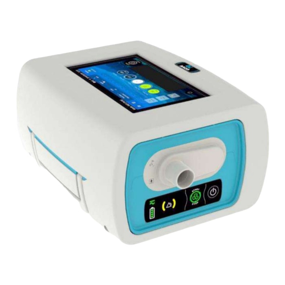
Chapter 1 – Description of the EO-70 device Front Panel 1. Display screen 3. EO device housing unit 2. SMD module 4. Circuit Port 5. Keyboard Rear Panel 1. Air inlet / outlet filters cover 5. USB-1 port 2. DC Power connector 6. -
Page 9: Rear View Of Device Without Housing
Rear view of device without housing USB port DC Power connector Connection to outer housing Keyboard 1. Power source indicator 2. Alarm indicators 3. Treatment start / stop button 4. Power on/off button 5. Battery level indicator... -
Page 10: Symbols Table
Symbols Table The following symbols may appear either on your product or its packaging. Keypad indicators / buttons Alarm indicator Battery level indicator AC/DC power indicator On/Off button Treatment start / stop button Touch interface symbols Treatment start Treatment stopping Menu access button Settings menu access button Return to Home Screen... - Page 11 USB connector Warning Remote control connector Applied part BF type Consult operating instructions Battery replacement warning: Only trained personnel can replace batteries International Protection Marking, IEC standard DC power inlet 60529. Protection against ingress of water and foreign objects. Date of manufacture This side up Manufacturer Complies with European legal requirements...
-
Page 12: Chapter 2 - Operating Instructions For The Eo-70 Device
4. Start treatment and verify air is coming in and out of the device outlet WARNING If any of these steps fails, do not use the EO-70 device. Contact your healthcare provider or your Eove representative for a device checking. -
Page 13: Turning On The Device
2. A confirmation message is displayed. Validate. 3. The device turns OFF. CAUTION The EO-70 device cannot be powered off during treatment Unplugging from mains power does not power off the device. It will continue to run on the internal battery. -
Page 14: Device Auto Power Off On Batteries
From the SMD module - Secondary proceedings 1. Press and hold for three seconds. 2. The SMD turns OFF. Device Auto Power off on batteries To keep the internal battery with the maximum autonomy, the device will automatically turn off after 15 min of inactivity. -
Page 15: Turning On And Off The Docking Station
The EO-70 device cannot be powered off during treatment Unplugging from mains power does not power off the device. It will continue to run on the internal battery. The device must be turned off manually before disconnecting from AC power for any extended period of time. - Page 16 4. Pull the module while maintaining the docking station with the other hand 5. To use the SMD module on standalone configuration, turn on the module and press the keypad to start and stop treatment according to the previously set parameters. 6.
-
Page 17: The Home Screen
The Home Screen On the home screen, there is important information about the settings, the pressure of treatment, the preset modes set up by clinician. The Home Screen is accessible from all other screens by pressing 1. Treatment mode indicator: Choose from 9. -
Page 18: Using The Touch Pad
Using the Touch Pad The Touch Pad is activated in INEX mode when set to MANUAL or in IPPB mode. INEX mode Manual operation In INEX mode, the operation must start in the Touch Pad black area but then the full screen surface can be used if the finger keeps the contact with the screen. -
Page 19: Navigating The Preferences Menu
Navigating the Preferences Menu From this screen the patient can change preferences. From the Home Screen, choose to access the Preferences and Maintenance menus. Press on Preferences to choose the Preferences Screen. (see below) From this screen the patient can adjust the following settings for the device. Rotation of screen Allows the screen to be rotated 180°. -
Page 20: Accessing The Settings Menu
Accessing the settings menu Do not access settings menu (unlocked mode ) unless directed by a physician. NOTE: To access the settings Menu 1. Choose and hold down the lock button, until it becomes red. A confirmation message is displayed. Validate. 2. -
Page 21: Presets
Presets The EO-70 device can store up to three different treatment presets. Presets can be configured by clinicians to provide personalized alternative treatment options. These preset configurations allow for different treatments. NOTE: If more than one preset has been set up, follow the instructions of your clinician for when and how they should be used. -
Page 22: Changing Preset Mode From Home Screen
Changing preset mode from Home screen 1. Available preset 2. Current preset / Activated preset 3. Empty preset To change the preset, click on the preset you want to switch on. Changing treatment mode From the settings menu, click the mode bar on the upper left of the screen. A pop up will be displayed to select the mode. -
Page 23: Changing Settings
Changing settings In list setting display mode, several settings changes can be validated at the same time. In the boxes display mode, each setting must be adjusted individually. List display mode 1. From the settings menu, click on one of the settings. 2. -
Page 24: Changing Preset Mode From Coaching Screen
NOTE: The coaching function is not available for all treatment modes. A message will indicate if something is missing to start the function. If the screen indicates no compatible preset is available, contact your service provider. Changing preset mode from Coaching screen 1. -
Page 25: The Inex Coaching Screen
The INEX Coaching Screen 1. Power off button 7. Battery life indicators: Indicates the level of 2. Preset mode menu (1-3): Presets installed by charge left in the battery or whether the the clinician and accessible to the patient battery is charging. when needed. - Page 26 During exhalation, chameleon deflates, and balloon inflates During pause, chameleon and balloon do not move. The monitorings: The peak flow is updated after each exhalation The cycle decounter decreases after each exhalation. It can be increased with the «+1» button during the last cycle ...
-
Page 27: The Ippb Coaching Screen
The IPPB Coaching Screen 1. Power off button 7. Date and Time with format YYYY/MM/DD 2. Preset mode menu (1-3): Presets installed by (can be changed in Preferences menu) the clinician and accessible to the patient 8. Leak indicator when needed. 9. - Page 28 For the 3 first inhalations: Chameleon does not move V Target stays undefined After 3 inhalations: V target is defined. It is the mean of the volume of the 3 first inhalations. It stays unchanged until end of the treatment. During exhalation, chameleon will gradually deflate until reaching the initial position and colour.
-
Page 29: Chapter 3 - Patient Circuit, Power Supplies And Accessories Configurations
Patient Circuit installation The EO-70 SMD device can be used with 22 mm diameter circuit only. It is recommended to use a bacterial filter at the outlet of the SMD device. - Page 30 INEX mode 1. Attach the antibacterial filter to the inspiratory port of the device. 2. Connect the breathing tube to the other side of the filter. 3. Perform a circuit calibration 4. Connect the patient interface to the other end of the breathing tube. IPPB mode 1.
-
Page 31: Patient Circuit Calibration
Patient circuit calibration For the EO-70 to provide expected performances, the patient circuit must be calibrated. The procedure detailed below includes two steps and corresponds to the IPPB mode. In the INEX mode case, calibration will only include the first step. - Page 32 In case of error during the seal or unseal phases, the following message will be displayed: Click then on “abort” to restart the process.
-
Page 33: Accessories Compatible With Eo-70
SPO2 Cable (EO-SPO2CBL) Remote control pedal (EO-70FSWITCH) The EO-70 can be used with 22 mm diameter breathing circuits complying with CE regulations. WARNING Before using any accessory, always carefully read the accompanying user Manual. The EO-70 device should only be used with accessories recommended by EOVE. Connection of other accessories could result in patient injury or damage to the device. -
Page 34: Attaching A Pulse Oximeter
Attaching a pulse oximeter WARNING Only use compatible NONIN finger pulse sensors CAUTION Some factors may degrade the performance of the pulse oximeter or affect the accuracy of the readings (e.g. blood flow restrictors (arterial catheters, blood pressure cuffs, infusing lines, etc.), excessive ambient light, excessive motion, electromagnetic interference, moisture in the sensor, improperly applied sensor, incorrect sensor type, a sensor not at heart level, poor pulse quality, venous pulsations, anemia or low hemoglobin concentrations, cardiogreen... -
Page 35: Attaching A Control Pedal
Attaching a control pedal 1. Connect the plug of the remote-control connector at the rear of the device. Locking Ring CAUTION To remove the cable, pull firmly on the locking ring. Do not twist. Upright Bracket installation for a vertical position of the device Insert the upright brackets into the guides located on the lower housing of the device. - Page 36 Push the upright brackets until full contact with the lower housing. Place the device on its upright brackets to use it on the vertical position CAUTION Make sure to push the upright brackets until the contact with the lower housing to ensure good support for the device Be sure to check the positioning of the upright brackets after moving the device...
-
Page 37: Power Connections
Make sure the power cord and plug are not damaged and the equipment is in good condition. Keep the power cord and device away from hot surfaces. Explosion hazard—do not use in the vicinity of flammable anesthetics. The EO-70 device can be used with two different power sources: Mains power ... -
Page 38: Running The Eo-70 On Internal Battery
The internal battery may stop charging when ambient temperatures of 35°C or more are reached. If the EO-70 device is left in storage for an extended period of time the internal battery will become depleted. If storing your device, recharge the internal battery once every four months. -
Page 39: Storing And Recharging
Chapter 4 – Alarms indicator The EO-70 is equipped with an alarm indicator to alert the user if the device is not functional for a technical reason. Those alarms are low priority (yellow indicator with no sound) and will all necessitate a technical support. -
Page 40: Chapter 5 - Routine Cleaning And Maintenance
Schülke or WILAsil® from WILAmed. For other product usage, please contact our customer service. Warning Proper cleaning and maintenance of your EOVE device is essential. Cleaning described in this section should be carried out regularly. Refer to the user guides of any accessories in use for detailed instructions specific to those devices. -
Page 41: Instructions For Hygienic Reprocessing At Patient Change
The EO-70 device external surfaces in contact with the disinfectant products are made with the materials listed below:... -
Page 42: Servicing
Retain the original packaging to use when shipping to/from service agent. Maintenance Timetable The EO-70 should be regularly serviced by an authorized EOVE technician according to the following schedule. The SMD device will provide safe and reliable functioning for 10 years provided that it is operated and maintained in accordance with the instructions given in this manual. -
Page 43: Essential Performances
Essential performances The EO-70 essential performances can be evaluated with this reference test : Settings: INEX Mode, Operating mode: AUTO, Inh. Pressure: 30 cmH2O, Slope: 3, Inh. Time: 3 s, Trigger : off, Pause : 1 s, Peep: 4 cmH2O, Exh. Pressure: - 30 cmH2O, Exh Time : 2 s, Insp. Oscillations I: on (Amp. -
Page 44: Chapter 6 - Device Information
WARNING INEX mode of EO-70 is designed for an intermittent use (non-continuous). The device has to be in stand-by for a duration equal to the preceding usage time (typical use of 1 min 30 sec should be followed by a minimum stand-by period of 1 min 30 sec). For clinical reasons, it is not recommended to exceed 5 minutes of continuous usage. - Page 45 Setting Range Limitations Operating mode AUTO / MANUAL In manual mode the insufflation and exsufflation are triggered by the user. Inh. Pressure (cmH2O) 5 - 70 None Slope 0 - 5 None Inh Time (s) 0.5 - 5 Only applies in AUTO mode. Insp.
-
Page 46: Accuracy Of Settings
Accuracy of settings Pressure (plateau) : ± (1 cmH2O + 10%) Pressure peaks : ± (2 cmH2O + 20%) Time : ± 0.2 s Flow : ± (5 l/min + 10%) Monitored Parameter Specifications (Rounded values for readings) Inspiratory Tidal Volume (VTI) 0 to 4000 ml Inspiratory Time (I Time) -
Page 47: Power Specifications
Power specifications WARNING This device is intended to function with external power supply 2440 from Mascot, never use any other power supply unless recommended by Eove. To disconnect the device from the mains, unplug power supply. AC Inlet Voltage 100-240V AC Inlet Power 1.6-0.7A... -
Page 48: Guidance And Manufacturer's Declaration Electromagnetic Emissions & Immunity
Guidance and Manufacturer’s Declaration Electromagnetic Emissions & Immunity WARNING The EO-70 should not be used in close proximity to other equipment or stacked on top of other devices. If this kind of use is unavoidable, the device should be checked carefully and observed to ensure correct functioning of the device. - Page 49 Electromagnetic immunity Immunity Test IEC 60601 level Level of compliance Guidance for EM environment Electrostatic discharge 8 kV contact 8 kV contact For home health care (ESD) environment and a 15 kV air 15 kV air professional health care IEC 61000-4-2 establishment Electrical fast 2 kV for power...
- Page 50 Immunity Test IEC 60601 level Level of compliance Guidance for EM environment Voltage Interruption 0 % UT 0 % UT IEC 61000-4-11 for 250 cycles at for 250 cycles at 50 50 Hz for 300 cycles at for 300 cycles at 60 60 Hz Power frequency (50/60 30 A/m...
- Page 51 Immunity Test IEC 60601 level Level of compliance Guidance for EM environment Proximity fields emitted 9 V/m : 710 9 V/m : 710 MHz, For home health care by RF wireless MHz, 745 MHz, 745 MHz, 780 MHZ, environment and a communication devices 780 MHZ, 5240 5240 MHz, 5500...
-
Page 52: Standards Compliance
Standards compliance The EO-70 meets the following standards: EN ISO 14971: Medical Device Risk Management IEC 60601-1 Ed3 (&CSA22.2): Medical Electrical Equipment –Part 1: General Requirements for Safety 1: Collateral Standard: Safety Requirements for Medical Electrical Systems The device is classified according to Chapter 5 of the norm CEI 60601-1, as follows:... -
Page 53: Training And Support
Training and support Training and support are available on the EOVE website, www.eove.fr or by calling our helpline at 05 59 21 86 84 Limited warranty The seller guarantees that the Product delivered complies with the use for which it is intended, and guarantees the Purchaser in this respect from defects in materials and workmanship. - Page 54 2020 EOVE. All rights reserved. Made in France. 0459 EOVE 4 bd Lucien Favre Bâtiment Poincaré 64000 Pau France www.eove.fr T +33 05 59 21 86 84...
Need help?
Do you have a question about the EO-70 and is the answer not in the manual?
Questions and answers