
Related Manuals for AE-Air HydroTech HRC Series

Summary of Contents for AE-Air HydroTech HRC Series
- Page 1 Installation, Operation, & Maintenance Manual IOM 787702 Rev. B 3/22 HRC(C,X) High Rise Series Water Source Heat Pump...
- Page 2 HRC(C,X) HIGH RISE SERIES - IOM COPYRIGHT AE-Air works to continuously improve its products and as a result, it reserves the right to change design and specifications without notice. The warranty may be void unless the Startup & Performance Checklist is completed and returned to the warrantor. If the HVAC unit is not installed properly, the warranty will be void, as the manufacturer cannot be held accountable for problems that stem from improper installation.
-
Page 3: Table Of Contents
– HRC(C,X) HIGH RISE SERIES TABLE OF CONTENTS SAFETY CONSIDERATIONS MODEL NOMENCLATURE GENERAL INFORMATION INTRODUCTION STORAGE SHIPPING & PACKAGE LIST 9-10 UNIT INSPECTION CHECKLIST UNIT DIMENSIONAL DATA 12-15 UNIT PHYSICAL DATA ELECTRICAL DATA INSTALLATION 18-28 CABINET CONFIGURATION 29-32 ELECTRICAL APPLICATION 34-35 CONTROLS 36-41... -
Page 4: Safety Considerations
HRC(C,X) HIGH RISE SERIES - IOM SAFETY CONSIDERATIONS 1. READ THE ENTIRE MANUAL BEFORE STARTING THE INSTALLATION. 2. These instructions are intended as a general guide and do not supersede national, state, or local codes in any way. 3. Altering the product, improper installation, or the use of unauthorized factory parts voids all warranty or implied warranty and may result in adverse operation and/or performance or may result in hazardous conditions to service personnel and occupants. - Page 5 – HRC(C,X) HIGH RISE SERIES SAFETY CONSIDERATIONS CONTINUED These instructions are intended as an aid to qualified, Mechanical components and filters can become clogged with licensed service personnel for proper installation, adjustment dirt and debris, which can cause damage to the system. and operation of this unit.
-
Page 6: Model Nomenclature
HRC(C,X) HIGH RISE SERIES - IOM SAFETY CONSIDERATIONS CONTINU MODEL NOMENCLATURE FIGURE 1 – Cabinet Model Nomenclature HRC(C,X) HIGH RISE SERIES – IOM (REV. B 3/22) - Page 7 – HRC(C,X) HIGH RISE SERIES MODEL NOMENCLATURE CONTINUED FIGURE 2 – Chassis Model Nomenclature HRC(C,X) HIGH RISE SERIES – IOM (REV. B 3/22)
-
Page 8: General Information
HRC(C,X) HIGH RISE SERIES - IOM GENERAL INFORMATION DO NOT use these units as a source of heating or cooling Extreme caution must be taken that no internal damage during the construction process. Mechanical components will result from screws that are drilled into the cabinet. and filters can become clogged with dirt and debris, which can cause damage to the system. -
Page 9: Storage
– HRC(C,X) HIGH RISE SERIES STORAGE Equipment should be stored in a clean dry, conditioned area with maximum temperatures up to 120°F [48.89°C] and minimum temperatures to 32°F [0°C]. Units should be stored upright and in an indoor environment. It is recommended to leave packaging on the unit until the installation is to begin. - Page 10 HRC(C,X) HIGH RISE SERIES - IOM SHIPPING & PACKAGE LIST Units Are Shipped FOB Factory Chassis can be shipped 2 ways. 1. Upright in carton 4 per pallet, see FIGURE 4 – Shipping Options 2. Upright inside cabinet (risers shipped separate or customer supplied) 4 per pallet, see FIGURE 4 –...
-
Page 11: Unit Inspection Checklist
– HRC(C,X) HIGH RISE SERIES UNIT INSPECTION CHECKLIST Complete the inspection procedures below before preparing unit for installation: 1) Visually inspect unit for any shipping damage. Damage must be reported immediately to the shipping company to make a claim. 2) Ensure that the carrier makes proper notation of any shortages or damage on all copies of the freight bill and completes a common carrier inspection report. -
Page 12: Unit Dimensional Data
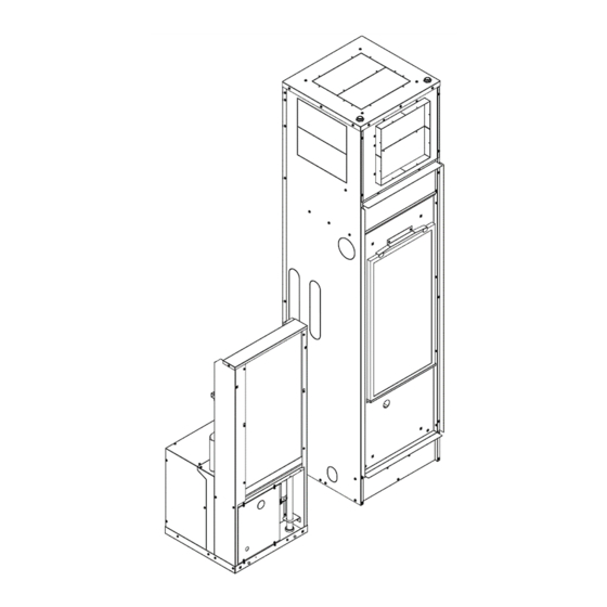
HRC(C,X) HIGH RISE SERIES - IOM UNIT DIMENSIONAL DATA FIGURE 7 – Unit Dimensions HRC(C,X) HIGH RISE SERIES – IOM (REV. B 3/22) - Page 13 – HRC(C,X) HIGH RISE SERIES UNIT DIMENSIONAL DATA CONTINUED FIGURE 8 – Unit Dimensions HRC(C,X) HIGH RISE SERIES – IOM (REV. B 3/22)
- Page 14 HRC(C,X) HIGH RISE SERIES - IOM UNIT DIMENSIONAL DATA CONTINUED FIGURE 9 – Unit Dimensions HRC(C,X) HIGH RISE SERIES – IOM (REV. B 3/22)
- Page 15 – HRC(C,X) HIGH RISE SERIES UNIT DIMENSIONAL DATA CONTINUED FIGURE 10 – Unit Dimensions HRC(C,X) HIGH RISE SERIES – IOM (REV. B 3/22)
-
Page 16: Unit Physical Data
HRC(C,X) HIGH RISE SERIES - IOM UNIT PHYSICAL DATA PHYSICAL DATA HRCC MODELS HRCC09 HRCC12 HRCC18 HRCC24 HRCC30 HRCC36 UNIT INFORMATION Compressor Type (Qty) Rotary (1) Scroll (1) Factory Charge (R410A) lbs. [oz] 1.7 [27] 2.7 [43] 2.7 [43] 3.7 [59] 3.7 [59] 3.6 [57] Motor (Qty) -
Page 17: Electrical Data
– HRC(C,X) HIGH RISE SERIES ELECTRICAL DATA ELECTRICAL DATA PSC BLOWER MIN. MAX. MODEL COMPRESSOR MOTOR VOLTAGE-PH-HZ CIRCUIT CIRCUIT NUMBER AMPACITY PROTECTION 208/230-1-60 1/12 HRCC09 265-1-60 1/15 208/230-1-60 0.65 1/10 HRCC12 265-1-60 0.65 1/10 208/230-1-60 HRCC18 265-1-60 208/230-1-60 10.9 62.9 HRCC24 265-1-60 208/230-1-60... -
Page 18: Installation
HRC(C,X) HIGH RISE SERIES - IOM INSTALLATION REQUIREMENTS Follow manufacturer’s installation instructions, as well as local and municipal building codes. Insulation is installed in the unit to provide a barrier INSTALLATION PRECAUTIONS between varying atmospheres outside and within the unit. ... - Page 19 – HRC(C,X) HIGH RISE SERIES INSTALLATION CONTINUED RISER & CABINET INSTALLATION Risers can be ordered loose, not attached to the cabinet, and shipped in bulk. Entire riser stacks can be assembled, pressure tested, flushed, and filled before setting cabinets. Insulate all drain risers and insulate all tubing for extended range applications (operation below 60 degrees F) or if condensation will occur on riser tubes.
- Page 20 HRC(C,X) HIGH RISE SERIES - IOM INSTALLATION CONTINUED RISER & CABINET INSTALLATION 1/4" (6.4mm) PITCH TOWARD DRAIN FROM DRAINAGE DRAIN CONNECTION Riser Transition Diameters FIGURE 12 – Riser Identification These units are for indoor installation ONLY! Do not locate unit in areas subject to freezing temperatures or where high humidity levels could cause cabinet condensation. Locate the unit in an area that provides minimum clearance accesses.
- Page 21 – HRC(C,X) HIGH RISE SERIES INSTALLATION CONTINUED CABINET WITH RISERS ATTACHED PERFORM HYDRISTATIC TESTING Each riser has a 3” flared opening at the top to accommodate the riser of the unit on the next floor. Check After all solder joints are made and all risers appropriately that riser is 3”...
- Page 22 HRC(C,X) HIGH RISE SERIES - IOM INSTALLATION CONTINUED RISER & CABINET INSTALLATION 1/4" (6.4mm) PITCH TOWARD DRAIN FROM DRAINAGE DRAIN CONNECTION FIGURE 13 – Typical Panel with “G” Panel Installation Position studs in front of cabinet and install frame in opening. Seal the gap between the cabinet and the frame. If a field installed fresh air motorized damper assembly is used, field fabricate and install duct from outside to frame opening.
- Page 23 – HRC(C,X) HIGH RISE SERIES INSTALLATION CONTINUED RISER & CABINET INSTALLATION For best sound attenuation, it is recommended not to attach drywall to cabinet. Install studs and drywall using conventional construction methods. Secure drywall to studs with low profile, pan-head sheet metal screws. Drywall can be attached directly to cabinet (FIGURE 13 –...
- Page 24 HRC(C,X) HIGH RISE SERIES - IOM INSTALLATION CONTINUED CONDENSATE DRAIN The Condensate drain must be in conformance with all plumbing codes. For Standard and Master Cabinets, the condensate drain between the drain pan assembly and condensate riser is factory installed, clamped, and trapped in the cabinet. For the slave cabinets.
- Page 25 – HRC(C,X) HIGH RISE SERIES INSTALLATION CONTINUED CHASSIS INSTALLATION After cabinets are installed and walls finished, remove the filter and inner panel of the cabinet, then remove plastic bag covering the inner panel. Never use flexible hoses of a smaller diameter than the water connections on the unit. Apply Teflon tape to the male ends of the hoses where necessary.
- Page 26 HRC(C,X) HIGH RISE SERIES - IOM INSTALLATION CONTINUED PIPING INSTALLATION All piping must be adequately sized to meet the designed water flow as specified for the specific application, and must adhere to all applicable codes. Piping connections on Check the condensate overflow sensor for proper the equipment are not necessarily indicative of the proper operation and adjust if necessary.
- Page 27 – HRC(C,X) HIGH RISE SERIES INSTALLATION CONTINUED PIPING INSTALLATION Ground loop applications require extended range equipment optional refrigerant/water circuit All manual flow valves used in the system must be ball Insulation. valves. Globe and gate valves must not be used due to high pressure drop and poor throttling characteristics.
- Page 28 HRC(C,X) HIGH RISE SERIES - IOM INSTALLATION CONTINUED LOW WATER TEMPERATURE CUTOUT SELECTION Disconnect power BEFORE the jumper wires are clipped. Failure to do so could result in equipment and/or property damage. For all applications, 50°F minimum entering water temperature and sufficient water flow is required to prevent freezing.
-
Page 29: Cabinet Configuration
– HRC(C,X) HIGH RISE SERIES CABINET CONFIGURATION AIRFLOW CONFIGURATION FIGURE 17 – Airflow Configuration HRC(C,X) HIGH RISE SERIES – IOM (REV. B 3/22) - Page 30 HRC(C,X) HIGH RISE SERIES - IOM CABINET CONFIGURATION ACCESS RETURN PANEL FIGURE 18 – Access Return Panel HRC(C,X) HIGH RISE SERIES – IOM (REV. B 3/22)
- Page 31 – HRC(C,X) HIGH RISE SERIES CABINET CONFIGURATION HOSE SPECIFICATION FIGURE 19 – Hose Specification HRC(C,X) HIGH RISE SERIES – IOM (REV. B 3/22)
- Page 32 HRC(C,X) HIGH RISE SERIES - IOM CABINET CONFIGURATION DISCHARGE AIR OPENING FIGURE 20 – Discharge Air Opening Top air discharge units will require turning vanes and/or a volume damper for proper airflow and balancing, to minimize turbulence. These components must be field furnished and installed in accordance with SMACNA guidelines.
-
Page 33: Electrical
– HRC(C,X) HIGH RISE SERIES ELECTRICAL HIGH VOLTAGE LOW VOLTAGE THERMOSTAT A standard 24 VAC Heat Pump thermostat is required that will operate the reversing valve in the cooling mode. Thermostat connections and their functions are below in as follows: FIGURE 21 –... -
Page 34: Application
HRC(C,X) HIGH RISE SERIES - IOM APPLICATION supply the proper flow rate for the unit. Nominal flow COOLING TOWER/BOILER APPLICATION rate is 3 GPM per 12,000 BTUH of cooling. To ensure optimum cooling and heating performance, the cooling tower and boiler loop temperature should be EXTENDED RANGE OPERATION maintained between 55-75°F in the heating mode and 60- 95°F in the cooling mode. - Page 35 – HRC(C,X) HIGH RISE SERIES APPLICATION CONTINUED WATER WELL APPLICATION REQUIREMENTS: 50° Minimum Entering Water Temperature Cupronickel Refrigerant Heat Exchanger When a water well is used exclusively for supplying water to the heat pump, a cupronickel refrigerant heat exchanger is required and the well pump should operate only when the heat pump operate.
-
Page 36: Controls
HRC(C,X) HIGH RISE SERIES - IOM CONTROLS SEQUENCE OF OPERATION FIGURE 17 – Sequence of Operations HRC(C,X) HIGH RISE SERIES – IOM (REV. B 3/22) - Page 37 – HRC(C,X) HIGH RISE SERIES CONTROLS CONTINUED WSCM CONTROL MODULE FIELD CONTROLLABLE FUNCTIONS TEST MODE CONTROL FEATURES The unit can be placed into test mode by shorting the test Anti-short Cycle Protection pins on the WSCM module. Once the pins are shorted, the ...
- Page 38 HRC(C,X) HIGH RISE SERIES - IOM CONTROLS CONTINUED FIELD CONTROLLABLE FUNCTIONS DEHUMIDIFICATION MODE HOME SELECTION The system can operate in Dehumidification mode by If the switch is in the HOME position the heat pump will switching Dip 1.4 on the WSCM module. In this mode, the operate in its normal mode .
- Page 39 – HRC(C,X) HIGH RISE SERIES CONTROLS CONTINUED WSCM SAFETY FEATURES CONDENSATE OVERFLOW SENSOR The condensate overflow sensor must sense overflow levels for 30 continuous second to initiate a COF fault. The condensate overflow sensor will be monitored during the compressor run cycle. LOW PRESSURE The low pressure switch must be open and remain open for 30 continuous seconds during the “on”...
- Page 40 HRC(C,X) HIGH RISE SERIES - IOM CONTROLS CONTINUED WSCM SAFETY FEATURES CONTROL BOARD LAYOUT LEGEND INPUT CONTROLLER OPERATION CODES CONNECTION DESCRIPTION DESCRIPTION OF OPERATION OUTPUT READOUT 24 VAC Normal Mode 24 VAC (Grounded Common) (Green Light) Input Call for Compressor Input Call for Heating or Emergency Heat Controller Non Functional (Green Light)
- Page 41 – HRC(C,X) HIGH RISE SERIES CONTROLS CONTINUED WSCM SAFETY FEATURES WSCM DIP SWITCH FUNCTIONS ASSEMBLY FUNCTION Once box is removed completely, line up the control panel DIP SWITCH 1 back in place of the unit and tighten screws on the base Compressor Delay No Delay 5s Delay...
-
Page 42: Performance Data
HRC(C,X) HIGH RISE SERIES - IOM PERFORMANCE DATA BLOWER DATA BLOWER DATA PSC FACTORY BLOWER BLOWER DATA SETTINGS CFM VS. STATIC PRESSURE (in. COOLING MODEL RATED w.g.) HEATING NUMBER SPEED AIRFLOW 1-10 HIGH 430 400 370 HRCC09 MEDIUM 360 340 310 280 250 280 250 220 HIGH 480 460 430 400 370... -
Page 43: Wiring Diagrams
– HRC(C,X) HIGH RISE SERIES WIRING DIAGRAMS HRC(C,X) HIGH RISE SERIES – IOM (REV. B 3/22) - Page 44 HRC(C,X) HIGH RISE SERIES - IOM WIRING DIAGRAMS HRC(C,X) HIGH RISE SERIES – IOM (REV. B 3/22)
- Page 45 – HRC(C,X) HIGH RISE SERIES WIRING DIAGRAMS HRC(C,X) HIGH RISE SERIES – IOM (REV. B 3/22)
- Page 46 HRC(C,X) HIGH RISE SERIES - IOM WIRING DIAGRAMS HRC(C,X) HIGH RISE SERIES – IOM (REV. B 3/22)
- Page 47 – HRC(C,X) HIGH RISE SERIES WIRING DIAGRAMS HRC(C,X) HIGH RISE SERIES – IOM (REV. B 3/22)
- Page 48 HRC(C,X) HIGH RISE SERIES - IOM WIRING DIAGRAMS HRC(C,X) HIGH RISE SERIES – IOM (REV. B 3/22)
- Page 49 – HRC(C,X) HIGH RISE SERIES WIRING DIAGRAMS HRC(C,X) HIGH RISE SERIES – IOM (REV. B 3/22)
- Page 50 HRC(C,X) HIGH RISE SERIES - IOM WIRING DIAGRAMS HRC(C,X) HIGH RISE SERIES – IOM (REV. B 3/22)
-
Page 51: Circuit Schematic
– HRC(C,X) HIGH RISE SERIES CIRCUIT SCHEMATIC FIGURE 30 - Circuit Diagram STARTUP INSTRUCTIONS PRE-STARTUP CHECKS: PRIOR TO THE STARTUP OF THE UNIT: 1. Ensure supply voltage matches nameplate data. 2. Ensure the unit is properly grounded 3. With the power off, check blower wheel set screws Electrically ground the unit. -
Page 52: Startup & Performance Checklist Instructions
HRC(C,X) HIGH RISE SERIES - IOM STARTUP INSTRUCTIONS CONTINUED 12. Verify water flow rate is correct according to PRIOR TO THE STARTUP OF THE UNIT: specification. Adjust if necessary. If specification is 9. Check that the water coil and piping had been leak not available, the nominal flow rate for this unit is checked and insulated as required. -
Page 53: Maintenance & Service
– HRC(C,X) HIGH RISE SERIES MAINTENANCE & SERVICE PREVENTIVE MAINTENANCE CLEANING/FLUSHING To achieve maximum performance and service life of Before the unit is connected to the supply water, the water equipment, a formal schedule of regular maintenance circulating system must be cleaned and flushed to remove should be established and adhered to. -
Page 54: Troubleshooting
HRC(C,X) HIGH RISE SERIES - IOM TROUBLESHOOTING PROBLEM POSSIBLE CAUSE CHECKS & CORRECTIONS Power supply off Apply power; close disconnect. Blown Fuse Replace fuse or reset circuit breaker. Check for correct fuses. If voltage is below minimum voltage specified on unit dataplate, Voltage supply low contact lower power company. - Page 55 – HRC(C,X) HIGH RISE SERIES TROUBLESHOOTING CONTINUED PROBLEM POSSIBLE CAUSE CHECKS & CORRECTIONS Unit oversized Recalculate heating and cooling loads. Thermostat installed near a supply air register, relocate thermostat. UNIT SHORT Thermostat Check heat anticipator. CYCLES Loose connections in the wiring or a defective compressor Wiring and controls contactor.
-
Page 56: Support/Reference Material
HRC(C,X) HIGH RISE SERIES - IOM SUPPORT/REFERENCE MATERIAL REFERENCE CALCULATIONS HEATING ABBREVIATIONS & DEFINITIONS LDB = EDB + LDB = Leaving air temperature dry bulb °F GPM x 500 EDB = Entering air temperature dry bulb °F LWT = EAT + GPM = Water flow rate gallons per minute cfm x 1.08 CFM = Airflow rate cubic feet per minute... -
Page 57: Startup & Performance Checklist
– HRC(C,X) HIGH RISE SERIES STARTUP & PERFORMANCE CHECKLIST FIGURE 31 – Startup and Performance Checklist HRC(C,X) HIGH RISE SERIES – IOM (REV. B 3/22) -
Page 58: Notes
HRC(C,X) HIGH RISE SERIES - IOM NOTES HRC(C,X) HIGH RISE SERIES – IOM (REV. B 3/22) - Page 59 – HRC(C,X) HIGH RISE SERIES NOTES HRC(C,X) HIGH RISE SERIES – IOM (REV. B 3/22)
- Page 60 Manufactured by: 8273 Moberly Lane Dallas, TX 75227 www.ae-air.com The manufacturer works to continually improve its products and as a result, it reserves the right to change design and specifications without notice. ©2021 AE-Air, 8273 Moberly Lane, Dallas, TX 75227...
Need help?
Do you have a question about the HydroTech HRC Series and is the answer not in the manual?
Questions and answers