
Related Manuals for AE-Air WSS6 Series

Summary of Contents for AE-Air WSS6 Series
- Page 1 Installation, Operation, & Maintenance Manual IOM 8302 Rev. A 04/21 WSS6 Series “Slim” Vertical Water Source Heat Pump 16 EER...
- Page 2 Altering the product or replacing parts with non-authorized factory parts voids all warranty or implied warranty and may result in adverse operational performance and/or a possible hazardous safety condition to service personnel and occupants. Company employees and/or contractors are not authorized to waive this warning. WSS6 SERIES – IOM (REV. A 4/21)
-
Page 3: Table Of Contents
STARTUP & PERFORMANCE CHECKLIST INSTRUCTIONS PERFORMANCE TABLES WIRING DIAGRAMS 28-31 CIRCUIT SCHEMATIC TROUBLESHOOTING 33-34 SUPPLEMENTAL DATA / TABLES 35-37 SUPPORT MATERIAL PREVENTATIVE MAINTENANCE STARTUP & PERFORMANCE CHECKLIST INDEX OF FIGURES INDEX OF TABLES WSS6 SERIES – IOM (REV. A 4/21) -
Page 4: Safety Considerations
CAUTION The CAUTION symbol indicates a potentially hazardous situation that may result in minor or moderate injury. NOTE Used to highlight suggestions, which may result in enhanced installation, reliability or operation. WSS6 SERIES – IOM (REV. A 4/21) -
Page 5: Model Nomenclature
Digit 18 – CABINET / SOUND OPTIONS 0 – Std Insulation Digit 11 – Heat Exchanger C – Copper Digits 19-21 – SPECIAL OPTIONS N – Cupronickel 000 – No Options Digits 22 – BRAND WSS6 SERIES – IOM (REV. A 4/21) -
Page 6: General Information
Installation of this equipment, wiring, ducts, and any property damage. related components must conform to current agency codes, state laws, and local codes. Such regulations take precedence over general instructions contained in this manual. WSS6 SERIES – IOM (REV. A 4/21) -
Page 7: Unit Dimensional Data
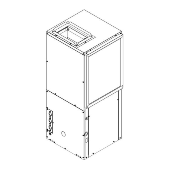
WSS6 Series UNIT DIMENSIONAL DATA FIGURE 3 - Right Top View FIGURE 2 - Dimensional Drawing FIGURE 4 - Left Top View FIGURE 6 - Return View FIGURE 5 - Front View WSS6 SERIES – IOM (REV. A 4/21) -
Page 8: Unit Physical Data
Throwaway Filter (Dimensions) 20x16 20x16 20x16 20x16 20x18 20x18 20x18 Throwaway Filter (Quantity) Weight – Operating (lbs) Weight – Packaged (lbs) Notes: FPT = Female Pipe Thread Table 3 – Unit Physical Data WSS6 SERIES – IOM (REV. A 4/21) -
Page 9: Electrical Data
8) Ensure that evaporator distributor tubes are not touching one in another and that they are over the drain pan. 9) Check the condensate sensor on the drain pan to make sure that it is rigid and attached. WSS6 SERIES – IOM (REV. A 4/21) -
Page 10: Installation Precautions
When soldering and brazing, it is recommended to have a fire extinguisher readily available. When soldering and brazing close to valves or sensitive components, heat shields or wet rags are required to prevent damage to the valves or components. WSS6 SERIES – IOM (REV. A 4/21) -
Page 11: Mounting Details
. 3/8”-1/2” vibration isolation FIGURE 8 - Mounting Illustration pads must be used to minimize vibration transmission. FIGURE 8 - Mounting Illustration WSS6 SERIES – IOM (REV. A 4/21) - Page 12 FIGURE 9 - Mount on High Platform Units should be mounted level on a solid platform no less than ¾” plywood or other related material with a proper drain pan pitch toward the condensate drain. WSS6 SERIES – IOM (REV. A 4/21)
-
Page 13: Piping
Refer to the project drawings and specifications for sizing. On units with plastic drain pans the drain connection must be made hand tight only. WSS6 SERIES – IOM (REV. A 4/21) -
Page 14: Ductwork
Follow the filter rack kit instructions & FIGURE 12 – Unit Ducting recommendations for installation. WSS6 SERIES – IOM (REV. A 4/21) -
Page 15: Electrical
All 208-240 Volt units are factory wired for 240 Volt operation. For 208 Volt operation, moving/changing/rewiring the line voltage tap on the 24 Volt control transformer is required. See note 3 on the wiring diagram for instruction. WSS6 SERIES – IOM (REV. A 4/21) -
Page 16: Application
Valves should be adjusted to supply proper water flow material can cause damage or failure to the water or to rated for the unit. refrigerant heat exchanger. Failure to do so will VOID ALL FACTORY WARRANTY. WSS6 SERIES – IOM (REV. A 4/21) - Page 17 The discharge water from the heat pump is not specialized training. contaminated in any manner and can be disposed of in various way depending upon local codes. WSS6 SERIES – IOM (REV. A 4/21)
-
Page 18: Controls
WSS6 Series - IOM CONTROLS SEQUENCE OF OPERATIONS FIGURE 14 - Sequence of Operations WSS6 SERIES – IOM (REV. A 4/21) - Page 19 If the LED display is flashing “Ay” the thermostat is not Test mode can be exited by shorting the test pins for set in cooling mode. approximately 3 seconds. NOTE Test mode will be automatically exited after a 10 minute period. WSS6 SERIES – IOM (REV. A 4/21)
- Page 20 RANDOM START HIGH PRESSURE The WSCM module features a 5-80s random start upon If the high-pressure switch opens at any time, the receiving a call to operate. compressor relay is de-energized immediately. WSS6 SERIES – IOM (REV. A 4/21)
- Page 21 Revering valve output terminals – direct connect from “O” COND_SW Condensate overflow input terminal Output terminal for electric heat FIGURE 15 - Control Board Layout Grounded common Table 7 - Control Board Layout Legend WSS6 SERIES – IOM (REV. A 4/21)
- Page 22 Vacated Premises DIP SWITCH 2 With Fan With Comp Accessory Relay Control None Compressor Delay With Fan With Comp Accessory Relay 2 Control None Fan Delay Table 9 - WSCM DIP Switch Functions WSS6 SERIES – IOM (REV. A 4/21)
-
Page 23: Control Box Detail
G1, G2, and G3, or by directly changing the speed tap at the motor terminal. NOTE High efficiency brushless DC motors are wired with power applied at all times, see illustration above. Low voltage thermostat demand and board algorithms will control its use. WSS6 SERIES – IOM (REV. A 4/21) -
Page 24: Refrigeration Slide Out Detail
NOTE: There may be multiple power sources supplying the unit. Condensing Section Weights Unit Weight (lbs) WSS6006 WSS6009 WSS6012 WSS6015 WSS6018 WSS6024 WSS6030 FIGURE 19 - Ebox Removal Table 10 – Condensing Section Weights WSS6 SERIES – IOM (REV. A 4/21) - Page 25 FIGURE 22 - Mechanical Fittings WARNING Do not pick up condensing section from unit piping or water-coil. Use the integrated handles on the condensing section base pan in order to lift the condensing unit. WSS6 SERIES – IOM (REV. A 4/21)
-
Page 26: Pre-Startup Checks
14. Verify that the water piping is complete and installation. correct. 15. Check condensate overflow sensor for proper operation and adjust position if required. WSS6 SERIES – IOM (REV. A 4/21) -
Page 27: Performance Tables
1150 1120 1090 1060 1030 MEDIUM-HIGH 1040 1010 WSS6030 MEDIUM Airflow data shown is with a dry coil at 70°F DB EAT and with standard 1” filter. Table 11 - WSS6 Blower Data WSS6 SERIES – IOM (REV. A 4/21) -
Page 28: Wiring Diagrams
WSS6 Series - IOM WIRING DIAGRAMS WSS6 SERIES – IOM (REV. A 4/21) - Page 29 WSS6 Series WIRING DIAGRAMS CONTINUED WSS6 SERIES – IOM (REV. A 4/21)
- Page 30 WSS6 Series - IOM WIRING DIAGRAMS CONTINUED WSS6 SERIES – IOM (REV. A 4/21)
- Page 31 WSS6 Series WIRING DIAGRAMS CONTINUED WSS6 SERIES – IOM (REV. A 4/21)
-
Page 32: Circuit Schematic
WSS6 Series - IOM CIRCUIT SCHEMATIC AP – ACCESS PORT HP – HIGH PRESSURE SWITCH LP – LOW PRESSURE SWITCH FIGURE 27 - Circuit Schematic WSS6 SERIES – IOM (REV. A 4/21) -
Page 33: Troubleshooting
The unit is low on refrigerant. Check for refrigerant leak, repair, Refrigerant charge evacuate and recharge with factor recommended charge. Low pressure switch Check for defective or improperly calibrated low pressure switch. Table 12 - Troubleshooting Table WSS6 SERIES – IOM (REV. A 4/21) - Page 34 The refrigerant system may be contaminated with moisture or non- Moisture, non- condensables. Reclaim refrigerant, evacuate and recharge with condensables factory recommended charge. Replace filter dryer. Table 13 - Troubleshooting Table Continued WSS6 SERIES – IOM (REV. A 4/21)
-
Page 35: Supplemental Data / Tables
19-25 17-21 178-188 346-366 34-40 16-20 134-144 331-351 19-25 8-12 203-213 370-390 38-44 8-12 140-150 459-479 18-24 15-19 Operation Not Recommended 140-150 426-446 18-24 7-11 Table 16 - WSS6012 Pressure & Temperature Data WSS6 SERIES – IOM (REV. A 4/21) - Page 36 21-27 18-22 181-191 384-404 36-42 15-19 126-136 337-357 21-27 8-12 203-213 405-425 40-46 7-11 134-144 515-535 19-25 18-22 Operation Not Recommended 132-142 448-468 20-26 7-11 Table 19 - WSS6024 Pressure & Temperature Data WSS6 SERIES – IOM (REV. A 4/21)
- Page 37 Table 20 - WSS6030 Pressure & Temperature Data WATER PRESSURE DROP WATER PRESSURE DROP (psi) DATA Entering Water Temperature °F MODEL WSS6006 WSS6009 WSS6012 WSS6015 WSS6018 WSS6024 WSS6030 Table 21 - Water Pressure Drop (psi) Data WSS6 SERIES – IOM (REV. A 4/21)
-
Page 38: Support Material
FOH = PSI x 2.3 Temperature °C = (°F – 32) x 5/9 Power kW = Btuh / 3412 Weight oz = lb x 16 Weight kg = lb / 2.2 COP x 3.413 EER / 3.413 WSS6 SERIES – IOM (REV. A 4/21) -
Page 39: Preventative Maintenance
MAINTENANCE UPDATES Check regularly for a current copy of the maintenance program log which can be found at under “product information”. WSS6 SERIES – IOM (REV. A 4/21) -
Page 40: Startup & Performance Checklist
WSS6 Series - IOM STARTUP & PERFORMANCE CHECKLIST FIGURE 28 - Startup and Performance Checklist WSS6 SERIES – IOM (REV. A 4/21) -
Page 41: Index Of Figures
WSS6 Series NOTES WSS6 SERIES – IOM (REV. A 4/21) -
Page 42: Index Of Tables
WSS6 Series - IOM NOTES WSS6 SERIES – IOM (REV. A 4/21) - Page 43 WSS6 Series NOTES WSS6 SERIES – IOM (REV. A 4/21)
- Page 44 Manufactured by: 8273 Moberly Lane Dallas, TX 75227 www.ae-air.com The manufacturer works to continually improve its products and as a result, it reserves the right to change design and specifications without notice. ©2021 AE Air, 8273 Moberly Lane, Dallas, TX 75227...
Need help?
Do you have a question about the WSS6 Series and is the answer not in the manual?
Questions and answers