
Related Manuals for Alpha Technologies Cordex 24-400W

Summary of Contents for Alpha Technologies Cordex 24-400W
- Page 1 Cordex 24-400W Rectifier Shelf System Technical Guide: 9400021-J0 Effective: 11/2018 Alpha Technologies Ltd.
- Page 3 Copyright Copyright © 2018 Alpha Technologies Ltd. All rights reserved. Alpha is a registered trademark of Alpha Technologies. No part of this documentation shall be reproduced, stored in a retrieval system, translated, transcribed, or transmitted in any form or by any means manual, electric, electronic, electromechanical, chemical, optical, or other-wise without prior explicit written permission from Alpha Technologies.
-
Page 5: Table Of Contents
ABLE OF ONTENTS ........1 AFETY Safety Wording/Symbols . - Page 6 Check for Damage ....... 13 Packing Materials ....... . 13 Returns for Service .
- Page 7 2RU, 24-400W, 19", 5 Module System ..... 42 Cordex 24-400W Switched Mode Rectifier ....43 CXCI HP Controller .
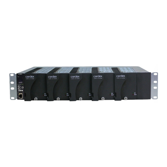
- Page 8 IST OF IGURES Figure 1: Four Module System, 030-763-20 ..... . 3 Figure 2: Five Module System, 030-773-20 ..... . 3 Figure 3: Rectifier Front Panel .
- Page 9 Specifications: 24-400W 19”, 5 Module System ....42 Table 11: Specifications: Cordex 24-400W, Switched Mode Rectifier ..43 Table 12:...
-
Page 11: Safety
Keep it in a safe place. Review the drawings and illustrations contained in this manual before proceeding. If there are any ques- tions regarding the safe installation or operation of this product, contact Alpha Technologies or the nearest Alpha representative. -
Page 12: Battery Safety
• A licensed electrician is required to install permanently wired equipment. Input voltages can range up to 240Vac. Ensure that the utility power is disconnected and locked out before performing any installation or removal procedure. • Ensure that no liquids or wet clothes come into contact with internal components. •... -
Page 13: Introduction
Cordex 24-400W integrated 19" shelf system with up to 2000W bulk output power. Product Overview A complete Alpha Technologies Cordex rectifier system consists of a controller with one or more power modules in a common shelf enclosure. The shelf has connections for AC inputs, DC output, and system communications. - Page 14 9400021-J0 Rev A Page 4...
-
Page 15: Features
Features Rectifier 3.1.1 Rectifier Front Panel Figure 3: Rectifier Front Panel 3.1.2 LEDs The front panel LEDs provide rectifier status summary and help to locate a specific module under CXC control. The top LED (green) is on when AC is within valid range and the rectifier is delivering power to the load. The LED will flash (~2Hz) when AC is outside the nominal range –... -
Page 16: True Module Fail Alarm
3.1.4 True Module Fail Alarm The power modules have a “true” fail alarm. This provides a true indication of the power module’s ability to source current. When the module’s output current drops below 2.5% of the rated output a low output current condition is detected and the Module Fail detection circuit is activated. -
Page 17: Current Limit/Short Circuit Protection
3.1.11 Current Limit/Short Circuit Protection The current limit function determines the maximum output current limit of the rectifier module, regard- less of output voltage or power. Maximum output current is limited to a constant value down to short circuit condition. Current limiting can be used to mate the rectifier output current ampacity to the needs of the load and parallel battery to minimize excessive battery recharge current. -
Page 18: Display
Figure 4: CXCI HP Controller Reset LED Screen Forward and Back Buttons to scroll through Menus and Select button to Execute System Status LEDs USB Port Ethernet Port 3.2.1 Display In dashboard mode, the in-shelf display shows the key operating parameters of a system. For example, output voltage and load current. -
Page 19: In-Shelf Display: Menu
3.2.2 In-Shelf Display: Menu From the OLED dashboard, use the Select button to enter a menu. From the menu, the OLED display lets you execute a set of commands much like the LCD screens on the CXC HP. When you enter a menu, the top item is highlighted. To go to another menu scroll through using the Forward and Back buttons. -
Page 20: Overview Of The Cxci
Figure 7: In-Shelf Controller Buttons M e n u A L C O A L C O R e s e t I P v 4 I P v 6 Back Select Forward Overview of the CXCI+ The CXCI+ has a 4-digit display for monitoring system voltage (V) and current (A). A pushbutton toggle switch allows the user to alternate the display reading. -
Page 21: Reset (Cxci+ Only)
Alarm Conditions The CXC illuminates the LED that corresponds to the alarm status. Only one LED is illuminated at a time during alarm conditions: • Green: OK, no alarms present • Yellow: Minor alarm is present (no major alarms) • Red: Major alarm is present. -
Page 22: Digital Input Channels
Temperature Inputs Two temperature input channels, T1 and T2, provide monitoring of battery temperature and temperature compensation (temp comp) or room/ambient temperature. A voltage is supplied to these terminals to power the temperature sensors. 3.4.3 Digital Input Channels The controller can accommodate up to two channels and can monitor digital alarm/control signals from rectifiers, converters and many other types of equipment. -
Page 23: Inspection
Alpha Technologies is not responsible for damage caused by improper packaging of returned products. If you have any questions before you proceed, call Alpha Technologies: 1 888 462-7487. 9400021-J0 Rev A... - Page 24 9400021-J0 Rev A Page 14...
-
Page 25: Installation
Installation Installation This chapter is provided for qualified personnel to install the product. Mount the unit horizontally in a clean and dry environment. : Drawings are located at the rear of the manual. NOTE : This system is designed to be installed in a restricted access location that is inaccessible to WARNING the general public. -
Page 26: Removing A Cxrc
Insert rectifiers by placing the module on the shelf bottom and sliding the module into the rear connector (inside of the shelf). Apply pressure on the front of the module to engage the rear connector in the shelf receptacle. A thumbscrew is provided to secure the rectifier into the shelf. : Do not force a module into position if it does not seat properly. -
Page 27: Figure 11: Removing The Cxci Hp
Figure 11: Removing the CXCI HP 1. Remove the screw from the front side controller. 2. Pull here to remove the controller from the shelf. 9400021-J0 Rev A Page 17... - Page 28 9400021-J0 Rev A Page 18...
-
Page 29: Wiring And Connections
Wiring and Connections Safety Precautions : Hazardous AC voltages may be present. Ensure power at the AC service panel is off before WARNING attempting work on the AC connections. Use a voltmeter to verify the absence of voltage. Clearly mark the correct polarity of the battery leads before commencing work on DC connections. -
Page 30: Ac Input
Table 2: Recommended AC Supply Configuration Circuit Breaker, 90 deg. C Wire Gauge Number of Rectifiers Exact Value to Use to use at 30 deg. C AC Input (Vac) on AC Feed ambient (AWG) 120/240 10 or 15 120/240 120/240 An external surge protection device is not required. -
Page 31: Dc Output
DC Output : Leave cables disconnected at battery and verify output polarity using a voltmeter. Make WARNING battery connections only after all other wiring is completed. DC output wire shall be UL approved XHHW or RHH/RHW (for Canadian users, RW90 Type). Control and sense wires shall be UL approved Style 1015 (for Canadian users, TEW type). -
Page 32: Ethernet Port For Local Connection
6.9.2 Ethernet Port for Local Connection Local access (e.g. laptop computer) is also possible from the Ethernet port connection using a standard network cable. : Older CXCI models must use a crossover Ethernet cable for direct connection to a computer. NOTE 6.10 Signal Wiring Connections... -
Page 33: Analog Inputs
Bundle the signal cables together and route them through the entry holes of the shelf. 6.10.1 Analog Inputs : Ensure the correct polarity is used for all input cable terminations. CAUTION The analog input channels are used to monitor various types of electrical signals. The Voltage Input is -60 to +60Vdc. -
Page 34: Alarm Relay Outputs
Figure 12: Digital Input Connection Method Programming the Digital Input The digital input channels can be programmed for “active high” or “active low. Active high indicates, “alarm on the presence of a ground signal” and active low indicates, “alarm on the removal of a ground signal.”... -
Page 35: Lvd Control Alternative
LVD Inhibit Should it be necessary to remove a CXCI series controller, the customer connection board (on the rear of the shelf) provides shorting pins (JP2) to inhibit (or override) the LVD Control function. See the customer connections drawings. If the LVD is controlled on NC contacts (factory default for LVD option), then JP2 pins 1 and 2 must be shorted together to maintain LVD operation. - Page 36 9400021-J0 Rev A Page 26...
-
Page 37: Operation
Operation Main Rectifier States Rectifier operation has five main states; each state is distinct and necessary for the operation of the rectifier. • • Start Delay • Soft Start • Normal Operation • Turning Off 7.1.1 The rectifier is in the Off state immediately after power is applied to the rectifier or after a rectifier shut- down (remote or local shutdown, AC shutdown, OVP or thermal shutdown). -
Page 38: Turning Off
7.1.5 Turning Off The Turning Off state is entered because a short delay is required before the rectifier actually turns off to take care of any initialization requirements. When this short delay has elapsed, a transition to the Off state is made. Main Rectifier Modes In addition to main rectifier states, there is a set of main rectifier modes. -
Page 39: Can Bus Communication
Table 6: Output Current/Power Modes (Continued) (Sheet 2 of 2) Output Current/Power Mode Output current and power limit have been reduced due to: Short circuit foldback Short circuit at the output. mode Internal fault foldback Internal fault. mode CAN Bus Communication The CAN bus is used for commands and data transfer between the rectifier and controller to configure the rectifier with system settings and to monitor rectifier status. -
Page 40: Table 7: Factory Ranges And Defaults
Table 7: Factory Ranges and Defaults (Continued) (Sheet 2 of 2) Setting Range (minimum to maximum) Default Current Limit / Power Limit Alarm Enable/Disable Enable Remote Shutdown Enable/Disable Enable Ramp Test Enable/Disable Enable : OVP cannot be set below the present system/FL/EQ/BT voltage setting or the safe mode voltage NOTE of 25.7V. -
Page 41: System Startup
System Startup Check System Connections • Ensure AC is off, battery is disconnected, and all power modules are removed from the shelf. • Verify the polarity of all connections. Verify AC and Power The Shelf • Install one power module. •... -
Page 42: Hard Reset
This reset allows local access; e.g., with a laptop and a standard network crossover cable. See current version software manual for details. : This does not apply to the CXCI HP. NOTE 8.4.3 Hard Reset A hard reset of the controller can be performed by pressing the front panel hard reset button. This proce- dure will restart the microprocessor if the front panel (soft) reset button fails to operate. -
Page 43: Maintenance
Maintenance Although very little maintenance is required with Alpha systems, routine checks and adjustments are recommended to ensure optimum system performance. Qualified service personnel should do repairs. The following table lists a few maintenance procedures for this system. These procedures should be performed at least once a year. - Page 44 3. Save the CXC text file if necessary: Logs and Files > Manage Editable Text Files > Save Dynamic Text File. If applicable, bypass the system LVD: a. Locate JP2 on the back of CXCI+ system shelf (see below). b. If the LVD is controlled on NC contacts (factory default for LVD option), then JP2 pins 1 and 2 must be shorted together to maintain LVD operation.
- Page 45 5. Place the new CXCI+ controller on the shelf bottom and slide into the rear connector at the back of the slot. 6. Log on to the controller and go to Logs and Files > Manage Configuration File > Upload Site Configuration and select the saved *.cfg file.
- Page 46 9400021-J0 Rev A Page 36...
-
Page 47: Warranty And Service Information
Warranty and Service Information 10.1 Technical Support In Canada and the USA, call toll free 1-888-462-7487. Customers outside Canada and the USA, call +1-604-436-5547. 10.2 Warranty Statement For full information details review Alpha's online Warranty Statement at www.alpha.ca. 10.3 Product Warranty Alpha warrants that for a period of two (2) years from the date of shipment its products shall be free from defects under normal authorized use consistent with the product specifications and Alpha’s instructions, the terms of the manual will take precedence.The warranty provides for repairing, replacing or issuing... - Page 48 9400021-J0 Rev A Page 38...
-
Page 49: Glossary
Glossary Alternating Current ACCT Alternating Current Current Transducer ADIO Analog-digital input-output ALCO Alarm cutoff Controller Area Network Current Transducer Cordex series; e.g. CXC for Cordex™ System Controller Cordex™ Controller CXC HP Cordex™ Controller High Performance Cordex™ DC-DC Converter Cordex™ Rectifier Direct current DCCT Direct Current Current Transducer... - Page 50 IPv4 Internet Protocol version 4 IPv6 Internet Protocol version 6 International Organization for Standardization Liquid Crystal Display Light Emitting Diode Low voltage disconnect LVBD Low voltage battery disconnect Media Access Control; e.g. MAC address Management Information Base; a database of entities most often associated with SNMP Metal Oxide Varistor Multiplexer NEBS...
-
Page 51: Specifications
Specifications 12.1 2RU, 24-400W, 19", 4 Module System Table 9: Specifications: 24-400W 19”, 4 Module System Specifications: 24-400W 19", 4 Module System Basic Unit: Shelf Maximum Output: 56A, 30VDC Recommended 20A, #12 AWG per feed Feed Breaker, Single Phase: Mechanical Dimensions: 88mm H x 444mm W x 307mm D, rectifier front panel 18mm D (3.5"... -
Page 52: 2Ru, 24-400W, 19", 5 Module System
Table 9: Specifications: 24-400W 19”, 4 Module System Specifications: 24-400W 19", 4 Module System * See drawings at the rear of this manual. The above information is valid at the time of publication. Consult factory for up-to-date ordering information. Specifications are subject to change without notice. -
Page 53: Cordex 24-400W Switched Mode Rectifier
Consult factory for up-to-date ordering information. Specifications are subject to change without notice. 12.3 Cordex 24-400W Switched Mode Rectifier Table 11: Specifications: Cordex 24-400W, Switched Mode Rectifier (Sheet 1 of 4) Specifications: Cordex 24-400W, Switched Mode Rectifier Power Module Output Voltage:... - Page 54 Table 11: Specifications: Cordex 24-400W, Switched Mode Rectifier (Continued) (Sheet 2 of 4) Specifications: Cordex 24-400W, Switched Mode Rectifier EMI: The unit meets requirements of EN55022(see Standards for more EMC) In accordance with FCC requirements, we provide the following statement as specified in the FCC...
- Page 55 Table 11: Specifications: Cordex 24-400W, Switched Mode Rectifier (Continued) (Sheet 3 of 4) Specifications: Cordex 24-400W, Switched Mode Rectifier Soft Start: User adjustable to at least 5 seconds (not including start-up delay time) and is determined by output current limit ramp-up T.H.D.
-
Page 56: Cxci Hp Controller
Table 11: Specifications: Cordex 24-400W, Switched Mode Rectifier (Continued) (Sheet 4 of 4) Specifications: Cordex 24-400W, Switched Mode Rectifier EN 61000-4-5: Power Line Surge Immunity EN 61000-4-6: Conducted Electromagnetic Immunity EN 61000-4-11 Voltage Dips, Short Interruptions and Variations ETS 300 019-1-1 Environmental Conditions;... - Page 57 Table 12: Specifications: CXCI HP Controller (Continued) (Sheet 2 of 3) Specifications: Basic Unit, CXCI HP EMC: The unit meets requirements of: • EN 300 386-2 EMC and EMR, Telecommunications Network Equipment Emissions: • EN 55022 Class B (CISPR 22) CFR47 (FCC) Part 15 Class B Immunity: •...
-
Page 58: Cxci+ Controller
Table 12: Specifications: CXCI HP Controller (Continued) (Sheet 3 of 3) Specifications: Basic Unit, CXCI HP Display: 5-line, LED matrix Front Panel Menu up and down, home and select buttons Controls: LED’s: System OK (Green) Power System Minor Alarm (Yellow) Power System Major Alarm / Controller Fail (Red) Audio: Built-in speaker for alarm and popup message tones 70dbl... - Page 59 Specifications: Basic Unit, CXCI+ <200mA @ 24Vdc MTBF: 1,500,000 hrs @30°C (86°F) ambient EMC: Radiated and Conducted Emissions :North America Regions • CFR 47, Part 15 Subpart B, Class B ICES-003 Issue 2, Rev 1, Class European Regions • EN 55022 Class B EN 300 386-2 EN61000-3-2;...
- Page 60 Specifications: Basic Unit, CXCI+ Environmental Temperature: -40 to 65°C (-40 to 149°F) standard @ 3000m (9843ft), derate to 55°C (131°F) @ 4000m (13124ft) Humidity: 5 to 95% non-condensing Elevation: -500 to +4000m (-1640 to 13124ft) Hardware Specifications CPU: Coldfire Display: 4 digit LCD Front Panel Display pushbutton toggle switch for voltage (V) or current (A), Reset switch (soft reset...
- Page 61 Specifications: Basic Unit, CXCI+ The above information is valid at the time of publication. Consult factory for up-to-date ordering information. Specifications are subject to change without notice. 9400021-J0 Rev A Page 51...
- Page 62 9400021-J0 Rev A Page 52...
-
Page 63: Certification
Certification CSA (Canadian Standards Association also known as CSA International) was established in 1919 as an independent testing laboratory in Canada. CSA received its recognition as an NRTL (Nationally Recognized Testing Laboratory) in 1992 from OSHA (Occupational Safety and Health Administration) in the United States of America (Docket No. - Page 80 Fax: +90 216 370 23 68 www.alphapower.mx www.alpha.com.tr Alpha Technologies Ltd. Due to continuing product development, Alpha Technologies reserves the right to change specifications without notice. 9400021-J0 (11/2018) Copyright © 2018 Alpha Technologies. All Rights Reserved. Alpha® is a registered trademark of Alpha Technologies.
Need help?
Do you have a question about the Cordex 24-400W and is the answer not in the manual?
Questions and answers