
Related Manuals for Alpha Technologies Cordex 12-250W

Summary of Contents for Alpha Technologies Cordex 12-250W
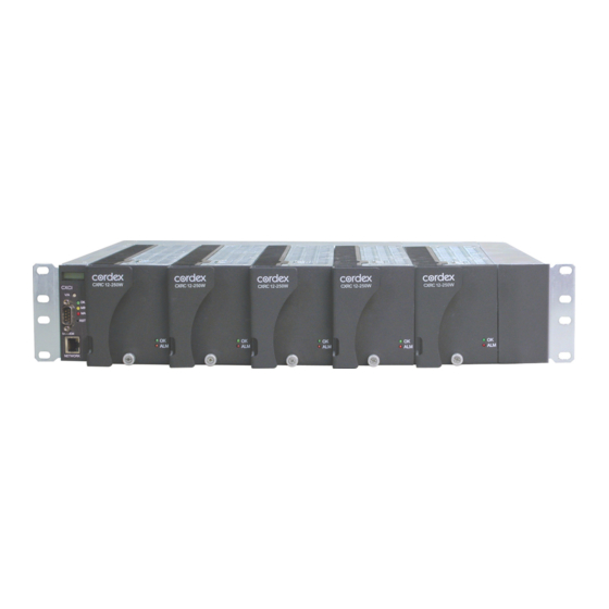
- Page 1 Cordex 12-250W 19" Integrated Shelf Up to 1250W with CXCI/CXCI+ Installation & Operation Manual Part # 030-818-B2 Effective: 10/2013 Your Power Solutions Partner member of The Group ™...
- Page 3 IMPORTANT SAFETY INSTRUCTIONS SAVE THESE INSTRUCTIONS 1. Please read this manual prior to use to become familiar with the product’s numerous features and operating procedures. To obtain a maximum degree of safety, follow the sequences as outlined. 2. This manual provides warnings and special notes for the user: a.
-
Page 4: Table Of Contents
ABLE OF ONTENTS ................................1 NTRODUCTION Scope of the Manual ............................. 1 Product Overview ............................1 Part Numbers and List Options ........................2 ................................... 3 EATURES Cordex Integrated System Controller (CXCI/ CXCI+) ................... 3 Rectifiers ............................... 6 Soft Start ............................... 7 .................................. -
Page 5: Introduction
Introduction Scope of the Manual This instruction manual explains the installation, interconnection, and operation of Alpha Technologies Cordex 12- 250W integrated 19" 2RU shelf with up to 1250W output power. The following documents and drawings are included in this manual: •... -
Page 6: Part Numbers And List Options
Description Part Number/List Option Cordex 12-250W 19" (flush mounting) 2RU shelf for systems up to 1250W (alt. #030-818-20) ....030-783-20 [equipped to receive one CXCI/ CXCI+ controller and up to five CXRC 12-250W rectifiers] ....... *List 0 120Vac input ................................ List 5 240Vac input ................................ -
Page 7: Features
Features Cordex Integrated System Controller (CXCI/ CXCI+) The CXCI/ CXCI+ controller is mounted in the rectifier system shelf and brings advanced monitoring technology to the Cordex series of rectifiers. This compact system controller is designed for seamless operation and set up of Alpha power systems and is equipped with the complete range of Cordex software features, including the following: •... - Page 8 System status LEDs LCD screen (V/A) Display pushbutton toggle Hard reset Soft reset: push once (push once) Reset IP address: hold for 3 seconds Ethernet port Figure 3–Cordex CXCI+ model system controller front panel 2.1.1.2 LEDs The controller has three LEDs located on the front panel. These are used to display the alarm status of the power system, CXC progress and status during startup, file transfers and lamp tests.
- Page 9 2.1.2 Analog Input Channels 2.1.2.1 Voltage Inputs Two voltage input channels, V1 and V2, provide monitoring of discharge and charge voltage. The CXC software is pre-configured to monitor V1 for load voltage and V2 for battery voltage. V2 (wired internally) is used as the system reference for rectifier float voltage, low voltage disconnect (LVD), system high voltage alarm, and system low voltage alarm.
-
Page 10: Rectifiers
Rectifiers Figure 4–Cordex 12-250W rectifier front panel 2.2.1 Front Panel LEDs The front panel LEDs provide rectifier status summary and help to locate a specific module under CXC control. 2.2.1.1 The top LED (green) is on when AC is within valid range and the rectifier is delivering power to the load. -
Page 11: Soft Start
detected and the Module Fail detection circuit is activated. This circuit momentarily ramps up the output voltage to determine if the module will source current. If no increase in current is detected, the Module Fail alarm is activated. The module will test once every 60 seconds for the condition until current is detected. Output voltage ramping will cease upon detection of current . - Page 12 2.3.3 Power Limiting Each rectifier module is designed to limit power output to the module specification. This enables more current to be supplied at lower output voltages, and allows matching of output to the demand of constant power loads, normally seen with telecom equipment. This feature may also be used for a faster recharge of flooded batteries paralleled with the load.
-
Page 13: Inspection
If the original container is unavailable, make sure the product is packed with at least three inches of shock-absorbing material to prevent shipping damage. NOTE: Alpha Technologies is not responsible for damage caused by the improper packaging of returned products. Check for Damage Prior to unpacking the product, note any damage to the shipping container. -
Page 14: Installation
Installation This chapter is provided for qualified personnel to install the shelf in a clean and dry environment. NOTE: To aid the user with installation, frequent reference is made to drawings located at the rear of the manual. Safety Precautions WARNING Hazardous voltages are present at the input of power systems. -
Page 15: Wiring And Connections
Wiring and Connections This chapter provides cabling details and notes on cable sizing for DC applications with respect to the shelf. NOTE: Refer also to foldout drawings located at the rear of the manual. Safety Precautions WARNING Hazardous AC voltages may be present. Ensure power at the AC service panel is off before attempting work on the AC connections. -
Page 16: Ac Input Connections
AC Input Connections CAUTION: AC input wires should be routed in flexible or rigid conduit as far away as possible from the DC power wires to minimize EMI disturbances. If the shelf is factory-equipped with a line cord, proceed to the next section. Refer to customer connections drawing 030-783-08 (rear view –... -
Page 17: Network Connection And Remote Communications Via Cxc
Network Connection and Remote Communications via CXC The Cordex system can be set up, monitored and tested via modem or ETHERNET 10/100 Base-T serial data connection. The communication protocol supports a web interface. Some standard scenarios are described below: 5.9.1 Modem Port (CXCI Controller Only) The Modem port is designed for CXCI connection to a user supplied modem via a front panel DB-9 connector. - Page 18 5.10.1 Analog Inputs for CXCI/ CXCI+ CAUTION: Ensure the correct polarity is used for all input cable terminations. The analog input channels are used to monitor various types of electrical signals. 5.10.1.1 Voltage Voltage Input #1 (load voltage per CXC software) terminals on the shelf (V1 on TB12) provide connections to an optional secondary voltage input.
- Page 19 5.10.2.2 Programming the Digital Input The digital input channels can be programmed for “active high” or “active low.” Active high indicates “alarm on the presence of a ground signal” and active low indicates “alarm on the removal of a ground signal.” See CXC Software manual for detailed instruction on programming.
-
Page 20: Operation
Operation Main Rectifier States Rectifier operation can be broken up into five main states: 1. Off, 2. Start delay, 3. Soft start, 4. Normal operation, 5. Turning off. Each state is characterized as being distinct and necessary for the operation of the rectifier. These states are briefly described below. -
Page 21: Main Rectifier Modes
Main Rectifier Modes In addition to Main Rectifier States, there is a set of Main Rectifier Modes. These modes can be divided into two categories as follows: 6.2.1 Output Voltage Modes Voltage modes can be thought of as modes that, under software control, can directly adjust the output voltage. The qualification of ‘under software control’... -
Page 22: Rectifier Factory Ranges And Defaults
Remote Shutdown Enable/Disable Enable Ramp Test Enable/Disable Enable Table F–Cordex 12-250W factory ranges and defaults NOTE: OVP cannot be set below the present system/FL/EQ/BT voltage setting or the safe mode voltage of 12.85V. 030-818-B2 Rev B Page 18 of 24... -
Page 23: System Startup
System Startup After completing the shelf wiring and installation, perform the following startup and test procedure to ensure proper operation: Check System Connections • Ensure AC is off, battery is disconnected, and all power modules are removed from the shelf. •... - Page 24 7.4.3 Hard Reset Refer to Figure 2 and Figure 3 on page 4 for the location of the hard reset button on the CXCI/ CXCI+. This can be used to restart the microprocessor in the event that the front panel (soft) reset button fails to operate as described in section 7.4.2.
-
Page 25: Maintenance
Maintenance Although very little maintenance is required with Alpha systems, routine checks and adjustments are recommended to ensure optimum system performance. Qualified service personnel should do repairs. The following table lists a few maintenance procedures for this system. These procedures should be performed at least once a year. - Page 26 6. Disconnect the DB signal connector from the CXCI. 7. Ensure a rectifier is in the right-most position. Remove the rectifier in the left-most position in order to access the side of the CXCI where the mounting screws are located. 8.
- Page 27 5. If applicable, bypass the system LVD: • Locate JP2 on the back of CXCI+ system shelf (Figure 7) • If the LVD is controlled on NC contacts (factory default for LVD option), then JP2 pins 1 and 2 must be shorted together to maintain LVD operation.
-
Page 28: 9.2 Acronyms And Definitions
Acronyms and Definitions Acronyms and Definitions Alternating current ANSI American National Standards Institute American wire gauge British thermal unit Controller area network Canadian Electrical Code Canadian Standards Association Cordex™ series; e.g., CXC for Cordex System Controller Direct current DHCP Dynamic host configuration protocol Electronic Industries Alliance Electromagnetic compatibility Electromagnetic interference... - Page 29 Consult the dealer or an experienced radio/TV technician for help. Alpha Technologies Ltd. 7400233-S0 Rev B Printed in Canada. © 2013 Alpha Technologies Ltd. ALPHA and CORDEX are trademarks of Alpha Technologies Ltd. All Rights Reserved. Page 1 of 3...
- Page 30 Ethernet RJ-45, Alpha Modem DB-9, CAN [see shelf specifications] CXCI+ Communication Ports: Ethernet RJ-45, CAN [see shelf specifications] Alpha Technologies Ltd. 7400233-S0 Rev B Printed in Canada. © 2011 Alpha Technologies Ltd. ALPHA and CORDEX are trademarks of Alpha Technologies Ltd. All Rights Reserved. Page 2 of 3...
- Page 31 The above information is valid at the time of publication. Consult factory for up-to-date ordering information. Specifications are subject to change without notice. Alpha Technologies Ltd. 7400233-S0 Rev B Printed in Canada. © 2011 Alpha Technologies Ltd. ALPHA and CORDEX are trademarks of Alpha Technologies Ltd. All Rights Reserved. Page 3 of 3...
- Page 32 Specifications for Alpha Cordex 12-250W 19" Integrated Shelf Basic Unit, Shelf Maximum Output: 105A, 15Vdc Recommended Feeder Breaker Single Phase: 15A, #14AWG Mechanical Dimensions: 88mm H x 444mm W x 307mm D (rectifier front panel 18mm D) [3.5" H x 17.5" W x 12.1" D (rectifier front panel 0.7" D)] Mounting*: 19"...
- Page 33 Any changes or modifications to this equipment not expressly described in this manual could void the FCC compliance. Alpha Technologies Ltd. 010-613-B1 (Alt. 010-587-B1) Rev B Printed in Canada. © 2013 Alpha Technologies Ltd. ALPHA and CORDEX are trademarks of Alpha Technologies Ltd. All Rights Reserved. Page 1 of 3...
- Page 34 (3.4" H x 2.8" W x 9.5" D) Weight: 2.9 kg (6.4 lb.) Alpha Technologies Ltd. 010-613-B1 (Alt. 010-587-B1) Rev B Printed in Canada. © 2013 Alpha Technologies Ltd. ALPHA and CORDEX are trademarks of Alpha Technologies Ltd. All Rights Reserved. Page 2 of 3...
- Page 35 The above information is valid at the time of publication. Consult factory for up-to-date ordering information. Specifications are subject to change without notice. Alpha Technologies Ltd. 010-613-B1 (Alt. 010-587-B1) Rev B Printed in Canada. © 2013 Alpha Technologies Ltd. ALPHA and CORDEX are trademarks of Alpha Technologies Ltd. All Rights Reserved. Page 3 of 3...
- Page 36 03078305A__.sch-1 - Fri Aug 04 13:28:50 2006 REVISION DESCRIPTION DATE APPD TB11 LVD AUTO OVERRIDE JUMPER BATTERY HOT BATTERY HOT K1 (LVD1) K2 (SYTEM MINOR) PCB ASSY, I/O INTERFACE, 19" SHELF 2RU, 5 MDL, CORDEX CXRC CUSTOMER TB12 PART NUMBER: 707-479-20 INTERFACE PCB ASSY, CXCI, MOTHERBOARD K3 (SYSTEM MAJOR)
- Page 37 REVISIONS DESCRIPTION DATE APPD REV BY UPDATED CXCI CONTROLLER LIST 99 CXCI-CONTROLLER LIST 19 - 6" OFFSET 010-587-20 CXRC POWER MODULE LIST 90 MODULE BLANK LIST 21 - FLUSH MOUNT LIST 80 SHOWN 19" RACK MOUNT OPTIONS LIST 99 CXCI-CONTROLLER THESE DESIGNS AND SPECIFICATIONS ARE THE PROPERTY OF ARGUS TECHNOLOGIES AND SHALL NOT BE COPIED OR USED FOR MANUFACTURING WITHOUT ITS WRITTEN CONSENT.
- Page 38 LIST 23 - 6" OFFSET LIST 19 - 6" OFFSET 12.1 307 12.1 307 6.0 152 6.0 152 LIST 25 - FLUSH MOUNT LIST 21 - FLUSH MOUNT 3.5 88 3.5 88 3.2 82 3.2 82 18.3 22.3 19.0 482 23.0 583 19"...
- Page 39 REVISIONS DESCRIPTION REV BY DATE APPD UPDATED CXCI MODULE 2006/09 G.S. DELETED NOTE FROM SHEET 3 2006/12 J.K. CHANGED AC I/P FROM 'L2' TO 'L2/N' 2007/04 J.K. CORRECTED JP2 PINOUT (SHT. 3) 2007/10 J.K. UPDATED NOTES 2008/01 J.K. LCD SCREEN (V/A) DISPLAY PUSHBUTTON TOGGLE SWITCH(V/A)
- Page 40 DC OUTPUT STUDS USES 1/4-20 x 5/8" OUTPUT LUGS TB3 FEEDS MODULES 1 AND 2 (TIGHTEN TO 8 ft-lbs) TB4 FEEDS MODULES 3, 4 AND 5 ( - ) L2/N L2/N ( - ) ( - ) AC CABLE ENTRY REAR VIEW 0.875"...
- Page 41 REAR VIEW (BACK COVERS REMOVED) L2/N L2/N ( - ) CUSTOMER CONNECTION BOARD DETAIL TB12 15 16 BATT NC C NO NC C NO NC C NO 12 11 10 9 TB11 REFER TO MANUAL FOR 1 2 3 4 JUMPER SETTINGS FOR JP2 TB13 THESE DESIGNS AND SPECIFICATIONS ARE THE PROPERTY OF...
- Page 44 Canada and USA: 1-888-462-7487 International: +1-604-436-5547 Visit us at www.alpha.ca Due to continuing product development, Alpha Technologies reserves the right to change specifications without notice. Copyright © 2013 Alpha Technologies. All Rights Reserved. Alpha® is a registered trademark of Alpha Technologies.
Need help?
Do you have a question about the Cordex 12-250W and is the answer not in the manual?
Questions and answers