Advertisement
INTRODUCTION
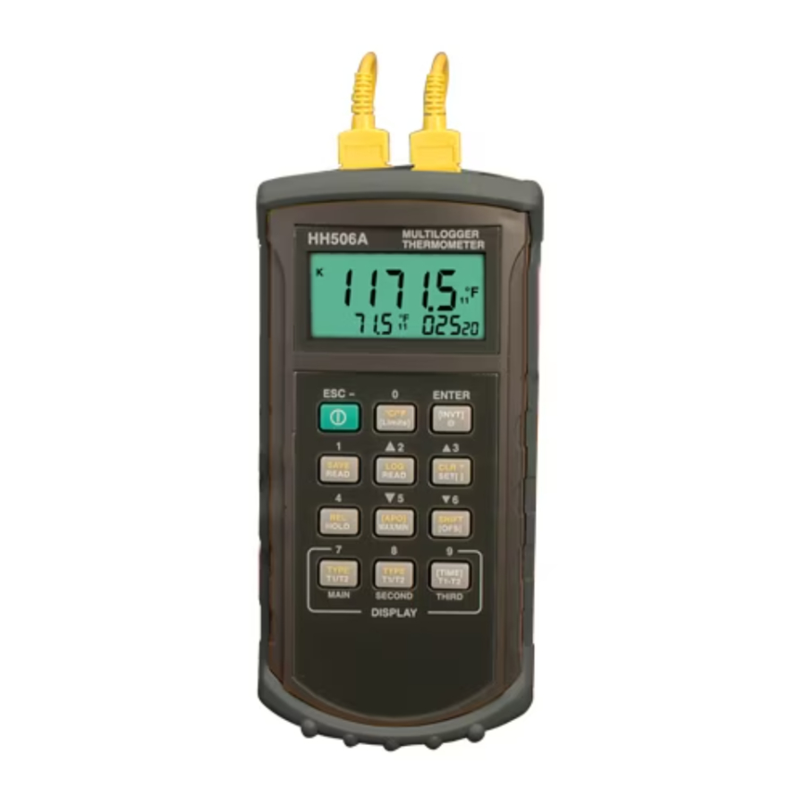
The HH506RA is a portable digital thermometer that measures external thermocouples of type K, J, R, S, T, E, and N. The thermocouple types comply with the NIST - ITS 90 standard reference temperature/voltage tables. The thermometer features a dual thermocouple input, an adjustable T/C offset and an RS-232 interface for uploading data to a PC using optional software and cable.
SAFETY INFORMATION
To avoid electrical shock do not use the device when the working voltages exceed 24V AC or DC. To avoid damages to the instrument and/or physical burns, do not make measurements in microwave ovens. Avoid sharp bending of the thermocouple leads to prolong its life, especially near the connector.

To avoid electrical shock, do not use this instrument when working voltages at the measurement surface are over 24V AC or DC.

To avoid damage or burns, do not take temperature measurements in microwave ovens.

Repeated sharp flexing can break the thermocouple leads. To prolong lead life, avoid sharp bends in the leads, especially near the connector.
GENERAL
Displays:
The Main and Second display panels are 4 1/2 digit liquid crystal display (LCD) with maximum reading of 19999. These panels are used for displaying the value of T1 or T2. The Third panel displays the date, time, or the difference value of T1 to T2. When the input measurement is overloaded, the following is displayed " ––––.–".
Battery:
Standard 9V battery (NEDA 1604, IEC 6F22 006P)
Battery life is about 100 hours when used with a carbon zinc battery.
Dimensions:
192 mm (H) x 91 mm (W) x 52.5 mm (D)
Weight: 365 g
Supplied Wire:
4 feet Type "K" thermocouple beaded wire (teflon tape insulated). Maximum insulation temperature 260C (500F). Wire accuracy 2.2C or 0.75% of reading (whichever is greater) from 0C to 800C.
ENVIRONMENTAL
Ambient Operating Ranges:
0C to 50C (32F to 122F) <80% R.H.
Storage Temperature:
-20C to 60C (-4F to 140F) <70% R.H.
Input Connector:
Accepts standard miniature thermocouple connectors (flat blades spaced 7.9 mm, center to center).
SPECIFICATIONS
ELECTRICAL
Temperature Scale: Celsius or Fahrenheit
Measurement Range:
| K-TYPE (0.1) | -200C to 1372C, -328F to 2501F |
| J-TYPE (0.1) | -210C to 1200C, -346F to 2192F |
| T-TYPE (0.1) | -200C to 400C, -328F to 752F |
| E-TYPE (0.1) | -210C to 1000C, -346F to 1832F |
| R-TYPE (1) | 0C to 1767C, 32F to 3212F |
| S-TYPE (1) | 0C to 1767C, 32F to 3212F |
| N-TYPE (0.1) | -50C to 1300C, -58F to 2372F |
*Based on the ITS-90 temperature standard.
According to temperature standard ITS-90.
Accuracy:
| K/J/T/E-TYPE | (0.05% rdg + 0.3C) on -50C to 1370C (0.05% rdg + 0.7C) on -50C to -210C (0.05% rdg + 0.6F) on -58F to 2501F (0.05% rdg + 1.4F) on -58F to -346F |
| N-TYPE | (0.05% rdg + 0.8C) on -50C to 0C (0.05% rdg + 0.4C) on 0C to 1300C (0.05% rdg + 1.6F) on -58F to 32F (0.05% rdg + 0.8F) on 32F to 2372F |
| R/S-TYPE | (0.05% rdg + 2C) on 0C to 1767C (0.05% rdg + 4F) on 32F to 3212F |
Temperature Coefficient:
0.1 times the applicable accuracy specification per C from 0C to 18 and 28C to 50C (32F to 64F and 82F to 122F)
Input Protecion:
24V dc or 24V ac rms maximum input voltage on any combination of input pins.
Reading Rate: 2.5 time per second.
Top Side:
- RS232 (Optical Interfaced) Port
- Sockets of thermocouples T1
- Sockets of thermocouples T2


OPERATING INSTRUCTIONS
Operational Mode
There are three operation modes–Normal, Shift, and Setup Mode.
Normal Mode:
This is the default mode; the operating functions for the normal mode are printed on the top of each button in white.
Shift Mode:
The operating functions for the shift mode are printed in yellow on the buttons. While in the normal mode, push the SHIFT button to switch to shift mode. At the lowerrighthand corner of the display panel, the word "Shift" is displayed to indicate shift mode. To switch back to normal mode, press the SHIFT button.
Setup Mode:
The operating functions for the setup mode are printed in between two bracket signs "[ ]" on each button. Press the SET[ ] button in normal mode to switch to setup mode, the indicator "SET" is shown on the left side of the display panel. To switch back to normal mode, press the SET[ ] button.
Normal Mode:
The following functions can only be used in the normal mode.
- "
![]() " Power Button
" Power Button
The"![]() " button turns the thermometer on or off. When entering data set mode, the power off function is disabled.
" button turns the thermometer on or off. When entering data set mode, the power off function is disabled. - "Limits" Button (only main display)
The limits function will alert the user when a measurement exceeds a specified limit. To set the limit values, refer to limits function in the setup mode.
Press the [Limits] button to activate the limits function; the word "LIMIT" should be displayed on the LCD.
When the value of the main display exceeds the Hi limit, the word "Hi" will be displayed and the thermometer will beep in an interval frequency. If the value of the main display is lower then the Lo limit, the word "Lo" will be displayed and the thermometer will beep in a continuous frequency. In Limits function, on K or J Type, and with the scale of temperature at °F, the reading counts should be times 10.
(ex: 2100°F means 21000 counts)
To exit the Limits function, press the [Limits] button. - "
![]() " button
" button
The backlight function is represented by this button "![]() ". Pressing the button will turn the backlight on or off in the LCD.
". Pressing the button will turn the backlight on or off in the LCD. - "SAVE/READ" button
The Read Data function works in conjunction with the Save function in the Shift mode, it is used for reading saved data. The Save function can be activated in Shift mode. Press the SAVE/READ button to activate the Read Data function; the word "READ" should be displayed on the LCD. To navigate around the Saved Data table, press the overlay "SECOND" button until the "#" sign is displayed on the second display panel. The location of the read pointer within the Saved Data table will be displayed. The arrow buttons on the overlay are used for scrolling through the saved data. Pressing the smaller arrow "![]() " or "
" or "![]() " retrieves the next saved data. Pressing the larger arrow "
" retrieves the next saved data. Pressing the larger arrow "![]() " or "
" or " ![]() " will retrieve the next ten saved data. Pressing the overlay "ESC" button deactivates the read data function.
" will retrieve the next ten saved data. Pressing the overlay "ESC" button deactivates the read data function. - "LOG/READ" button
The Log/Read function works in conjunction with the log function, it is used for reading the log data. The log function can be activated in the shift mode. Press the LOG/READ button to activate the read log function; the word "READ" should be displayed on the LCD. Press the overlay SECOND button to rotate through following display menus:
T1, T2, GRP, and #.
T1 and T2: Displays the T1 or T2 saved value.
GRP: Displays the current group number.
#: Displays the current location of the read pointer within a selected group. The arrow buttons on the overlay are used for scrolling through the data and groups. Press the smaller arrows "![]() "or "
"or "![]() " to retrieve the next log data or group. Press the larger arrows "
" to retrieve the next log data or group. Press the larger arrows "![]() " or "
" or "![]() " to retrieve the next ten log data or groups. To navigate around the log data and groups, press the overlay SECOND button till GRP appears in the second display panel, and then select the group using the arrows, then press the SECOND button again till the "#" sign is displayed. The location of the read pointer in the selected group will be displayed, and then use the arrows to scroll through the data. Pressing the overlay "ESC" button deactivates the read data function.
" to retrieve the next ten log data or groups. To navigate around the log data and groups, press the overlay SECOND button till GRP appears in the second display panel, and then select the group using the arrows, then press the SECOND button again till the "#" sign is displayed. The location of the read pointer in the selected group will be displayed, and then use the arrows to scroll through the data. Pressing the overlay "ESC" button deactivates the read data function.
 " Power Button
 " button
 " or "
 " retrieves the next saved data. Pressing the larger arrow "
- HOLD mode (only main display)
When HOLD mode is selected, the thermometer holds the present readings and stops all further measurements. To activate the data hold mode, press the HOLD button, and "HOLD" is displayed on the LCD. Pressing the HOLD button again cancels the function, and the instrument will automatically resume measurements. - MIN/MAX with time record mode (only main display)
The MIN/MAX function records the highest and lowest value recorded, and it calculates the average reading, and the differences of MAX to MIN. Press MIN/MAX button to enter the MIN/MAX recording mode. The beeper emits a tone when a new minimum or maximum measurement is recorded. Press the MIN/MAX button again to rotate through the current readings:
MAX: The highest measurement recorded.
MIN: The lowest measurement recorded.
MAX-MIN: The difference of the highest and the lowest measurement.
AVG: The average values of the measurements. This mode works in conjunction with the hold function, pressing the HOLD button will stop the recording and measurements (Previously recorded readings are not erased). Press HOLD button again to resume recording and measurements. To prevent accidental loss of MIN, MAX and AVG data, the MIN/MAX function can only be cancelled by pressing and holding down the MIN MAX key for more than 2 seconds. The Automatic Power Off function, and the power, C/F, REL, SET, Hi/Lo Limits, TYPE, T1/T2 buttons are also disabled.
- "T1/T2" button (MAIN display)
The input selection button [T1/T2] selects the input for the main display panel, T1 thermocouple or T2 thermocouple. Press the T1/T2 button to switch between the two inputs. When meter is turned on, it is set to the display that was last in use. - "T1/T2" button (SECOND display)
The input selection button [T1/T2] selects the input for the second display panel, T1 thermocouple or T2 thermocouple. Press the T1/T2 button to switch between the two inputs. When meter is turned on, it is set to the display that was last in use. - "T1-T2/TIME" button (THIRD display)
The input selection button [T1/T2] selects the system time and date, or the differential between the two thermocouples (T1-T2) for the third display panel. Press the T1/ T2 button to switch the display options. When meter is turned on, it is set to the display that was last in use.
SHIFTMODE
The following functions can only be used in the shift mode.
- "C/F" button
Press the C/F button to select the temperature scale, readings can be displayed in Celsius (C) or Fahrenheit (F). When the thermometer is turned on, it is set to the temperature scale that was last in use.
- "SAVE" button
The save function stores the T1, T2 data in nonvolatile memory. Press the SAVE button to save the current data. The word SAVE is displayed to indicate the data are saved. The build in memory can store up to 128 data. The data can be read using the read function in the normal mode. - "LOG" button
The data log function continuously records the data according to a specified time interval. The time interval can be set using the interval time setup function [INVT] in the setup mode. Press the LOG button to activate the log function; the indicator "LOG" and "MEM" will be displayed on the LCD. There are 16 groups that are used for storing the log data, and each group uses 64 data slots. If the current log session exceeds 64 data, the log function will automatically use the next group to store the following data. A maximum of 1024 data can be saved in one log session. Press the LOG button again to exit the data log function. - "CLR?" button
The CLR function clears all the saved and logged data in memory. When the CLR button is pressed, indicator "MEM" is displayed and the "CLR" word on upper-right of LCD will blink. Pressing "ENTER" button printed on the overlay in white word to clear all saved and logged data or "ESC" button to exit this function. - "REL" button (only main display)
The relative value function can be used for comparing the saved reference value with other measurements. Press the "REL" button to store the current measurement as the reference value, and the "REL" should be displayed on the right part of the LCD. The next measurement will display the relative value compared to the reference value. Press "REL" button again to clear the reference value and deactivate the relative value measurement function. - "[APO]" button
Press the [APO] button to trigger "Auto power off" function on or off. In this function, the indicator "APO" is shown at the upper lefthand panel of the LCD. When APO (Auto power off) is enabled, it will automatically turn the thermometer off if the key switch is inactivated according to to the set time (the default time for APO is 5 minutes). Press the Power button to resume operation.
- "TYPE" button (MAIN)
Press this button to change the type of thermocouple in the main display (K/J/T/E/R/S/N). If the inputs of the main and second displays are the same, then pressing this button will change the thermocouple type for both displays. - "TYPE" button (SECOND)
Press this button to change the type of thermocouple in the second display (K/J/T/E/R/S/N). If the inputs of the main and second display are the same, then pressing this button will change the thermocouple type for both displays.
SETUP MODE
The following functions can only be used in the setup mode.
- "[Limits]" button (Hi/Lo limit setting) and Mini DIN output
Press the LIMITS button to enter the Hi/Lo Limit setup function, the "LIMIT", "HI", and main display will blink on the LCD, and the previous settings are displayed. Press the number button printed on the overlay in white to set Hi or Lo limit value. the resolution of Hi/Lo limit setup is 1 count. The button "-" (same button as the ESC) can be used to set negative values. Setting is from left to right digit. Press the "ENTER" button to confirm each setting. - "[INVT]" button (Interval time setting)
To setup the time interval for the log function, press the [INVT] button to set the time. The indicator "INV" will be blinking on the topright of the LCD and the previous settings will be displayed. Press the number button printed on the overlay in white to change the time interval. Setting is from left to right of the following format (HH:MM:SS). Press the overlay "ENTER" button to confirm. To exit this function, press the ESC button.
HH: Interval Hour (0~23)
MM: Interval Minute (0~59)
SS: Interval Second (0~59)
MAX: 23:59:59 MIN:00:00:01
- "[APO]" button (Auto power off /time setting, min.5 minutes)
Use this function to change the time for the Auto Power Off (APO) function. Press the [APO] in setup mode, and the indicator "APO" and the main display will blink on the LCD, and the previous setting will be displayed. The default time for APO is 5 minutes. Press the Number button printed on the overlay in white to set the APO time. Press the overlay "ENTER" button to confirm. To exit this function without changing the setting, press the ESC button.
- MAX: 19999 minutes
MIN: 0005 minutes - "[OFS]" button (Thermocouple offset adjust)
When the main display input is T1 and socket thermocouple is connected, the instrument can adjust the offset of the thermocouple or vice-versa for T2. In the setup mode, press this button to enter the thermocouple Offset Setup
Function (OFS) and the indicator CAL should be displayed on the top righthand corner of the LCD while the main display blinks. While the previous setting is displayed, press the Number button printed on the overlay in white to change or set the offset of the thermocouple. The resolution of the setup is 0.1. Press the "-" button to set the negative value. Press the overlay "ENTER" button to confirm. MAX: 1999.9 C/F
- "[TIME]" button (System date and time setting)
To set or change the system time, press the [TIME] button in the setup mode. The time and date on the third display panel should blink. Enter from left to right in the following format: YY:MM:DD and HH:MM:SS. Press the Number button printed on the overlay in white word to set the system date and time. Press the "ENTER" button to confirm. Exit this function by pressing the ESC button.
PROCEDURE OF CALIBRATION
- Make ADJ pin short.
- T2 input for a voltage of 70mV will show a value higher than 28000 2dgts at the third display and then press "set[]" key in the next step.
- T1 input for a temperature of 0C will show a value 5C at the main display. Press "set[]" key to complete the calibration.
- Take off the short pin.
OPERATOR MAINTENANCE
To avoid possible electrical shock, disconnect the thermocouple connectors from the thermometer before removing the cover.
Battery Replacement
Power is supplied by a 9 volt "transistor" battery. (NEDA 1604, IEC 6F22). The " " appears on the LCD display when replacement is needed. To replace the battery, remove the two screws from the back of the meter and lift off the battery cover. Remove the battery from battery contacts.

Documents / ResourcesDownload manual
Here you can download full pdf version of manual, it may contain additional safety instructions, warranty information, FCC rules, etc.
Download Omega HH506RA - K, J, T, E, R, S, N Thermometer Manual
Advertisement


Need help?
Do you have a question about the HH506RA and is the answer not in the manual?
Questions and answers