Table of Contents

Related Manuals for Teka Filtercube 2-IFA


Summary of Contents for Teka Filtercube 2-IFA
- Page 1 Operating instructions (Translation of the original operating instructions) Filtercube 2 - IFA TEKA Absaug- und Entsorgungstechnologie GmbH, Industriestraße 13, D-46342 Velen, Tel.: +49 2863-9282-0, E-Mail: info @ teka.eu , www.teka.eu...
-
Page 2: Table Of Contents
7.3 Replacing the filter cartridges 7.4 Emptying the dust collecting tank 7.5 Draining the condensate 7.6 Precoating of new filter cartridges 7.6.1 Feeding the precoat via a FVS (TEKA spark pre-separator) 7.7 Cleaning the copper baffle plate 8 Dismantling / Disposal BA_Filtercube_2_IFA_171120_EN... - Page 3 9 Diagnostics and troubleshooting 10 List of spare parts 11 Technical data 12 EC declaration of conformity 13 Training protocol 14 Maintenance intervals 14.1 Usage-related maintenance 14.2 General maintenance 14.2.1 Visual inspection of the device 14.2.2 Visual inspection of the pipelines for dust deposits 14.2.3 Visual inspection of the pneumatic pipes 14.2.4 Functional test of the device 14.2.5 Electrical test of the electrical lines and earthing connections...
-
Page 4: General
1 General Congratulations on purchasing the product from TEKA. Our engineers ensure that our devices reflect the state of the art through continuous development. Nevertheless, misuse or misconduct can endanger your safety. Please observe the following for a successful use of the device: Only authorised and instructed personnel can carry out transport, operation, maintenance and repair of the device. -
Page 5: Description Of The System Elements
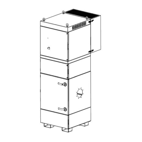
2 Description of the system elements 2.1 Illustration of the system elements Z.Nr. 04523702 Pos.1 Dust collecting housing Pos.6 Suction nozzle Pos.2 Filter housing Pos.7 Exhaust grille Pos.3 Cleaning housing Pos.8 Connection for compressed air Pos.4 Fan housing Pos.9 Drain valve for compressed air Pos.5 Silencing housing BA_Filtercube_2_IFA_171120_EN... -
Page 6: Functionality Of The System
2.2 Functionality of the system The filter unit serves to suck off and filter polluted air (according to the intended use). The air is purified on the surface of the filter cartridge in the filter section of the unit. The separated dust is collected in a dust collecting tank. -
Page 7: General Safety Instructions
3.2 General safety instructions WARNING Dangers arising from improper use / unauthorised operations. The operator must ensure that their authorised personnel are familiar with all the safety indications in this manual in advance. The operator is responsible for ensuring that all work is carried out by authorised and qualified personnel. -
Page 8: Storage, Transport And Installation Of The Device
4 Storage, transport and installation of the device WARNING Risk of injury from tilting or unmounted components when stored or transported. The device must be secured against tilting and slipping when it is stored or transported. Do not stand under or next to the floating load. Lift trucks, forklift trucks and transport cranes must have a sufficient minimum load bearing capacity. -
Page 9: Commissioning
Only operate the system if the necessary suction line is fitted. The suction line must be dimensioned according to the application. If this has not already been carried out by TEKA, a suitably qualified employee must be consulted. If the suction line includes extraction elements (e.g. -
Page 10: Assembly Of The Silencing Housing
5.1.1 Assembly of the silencing housing The silencing housing (see chapter 2.1) is supplied unassembled and must be assembled to the fan housing. ● Screw the two supplied flat-head screws DIN 923 M6x16 (B) into the matching threads. ● The silencing housing (A) is hung up on top on the two flat-head screws (B). ●... -
Page 11: Electrical Connection
5.2 Electrical connection WARNING Risk of electric shock. Electrical plants and equipment may only be built, modified and maintained by a qualified electrician or under the direction and supervision of a qualified electrician. Do not work on live electrical components and elements if you are not sure that these are indeed disconnected. -
Page 12: Precoating Of The Filter Cartridges
5.3 Precoating of the filter cartridges For a longer service life of the filter cartridges they are pretreated with a filter aid (precoat) in the factory. When the operator orders and installs new filter cartridges, we recommend to also precoat them before the commissioning. -
Page 13: Operating The System
6 Operating the system 6.1 Explanation of the operating elements Control functions, setting options for programs, menu navigation, error messages, etc. are described in the enclosed operating manual of the unit control. There is also an explanation of the elements of the control panel. Operating elements for the device control Representa Designation... -
Page 14: Maintenance
7 Maintenance In accordance with national regulations, t he operator is obliged to carry out repeat and functional tests. Unless otherwise specified by national regulations, we recommend regular visual inspections and functional tests of the device as described in the chapter “Maintenance intervals”. You find the chapter “Maintenance intervals”... -
Page 15: Reset To Maintenance State
7.1 Reset to maintenance state Filtercube 2H (resp. Filtercube 2 with external steering) : ● Switch off the unit. Then disconnect the unit from the power supply by setting the main switch in the “OFF” position. Secure the unit against unauthorized restarting during maintenance. ●... -
Page 16: Cleaning The Filter Cartridges
7.2 Cleaning the filter cartridges CAUTION A sudden jet of compressed air and huge amounts of whirled up dust are possible due to an automatic cleaning with an opened service door. During the operation of the device, the service door of the filter housing must not be opened. The same applies to the ready to operate condition (standby) as there is also the possibility of an automatic cleaning (subsequent cleaning). -
Page 17: Replacing The Filter Cartridges
7.3 Replacing the filter cartridges Replacing the filter cartridges becomes necessary when the filter cartridges are saturated with dirt in a manner that despite of the cleaning the filter alarm is triggered again at very short intervals or permanently. (The filter alarm is described in chapter “Cleaning the filter cartridges”.) CAUTION Whirling up dust is possible due to the polluted filter cartridges. - Page 18 Otherwise, a replacement seal must be used (see list of spare parts). ● Push the new filter cartridge into the cartridge holder. Only use TEKA spare filters. Otherwise the proper functioning of the unit is not guaranteed. ● Fasten the clamping screw of the cartridge holder.
-
Page 19: Emptying The Dust Collecting Tank
Before emptying the dust collecting tank hold ready an appropriate container (e.g. PE bag). The bags are optionally available at TEKA, see list of spare parts. We recommend having PE bags in stock. ●... -
Page 20: Draining The Condensate
7.5 Draining the condensate Operation with compressed air can result in condensation water being gradually deposited in the compressed air tank. The condensed water must be emptied regularly. The maintenance interval depends heavily on the quality of the compressed air and cannot, therefore, be determined in advance. CAUTION When opening the drain valve a blast of compressed air is possible. -
Page 21: Precoating Of New Filter Cartridges
● Provide sufficient filter aid. We recommend using 1 0 grams for each s quare metre of the f ilter surface . The filter aid is available at TEKA (see list of spare parts). ● Choose the capture point in the suction pipe that is the closest to the filter cartridges. E.g. an inspection flap can be used as a capture point. -
Page 22: Feeding The Precoat Via A Fvs (Teka Spark Pre-Separator)
7.6.1 Feeding the precoat via a FVS (TEKA spark pre-separator) This chapter is only relevant if the filter unit is equipped with a FVS (TEKA spark pre-separator). A FVS is a water separator installed in the suction pipe of the filter unit. -
Page 23: Cleaning The Copper Baffle Plate
7.7 Cleaning the copper baffle plate The copper baffle plate allows the air to circulate and therefore protects the filter cartridges. The copper surface also helps break up and extinguish any sparks that may be sucked in. In order to maintain this function, it is necessary to clean the copper baffle as required. -
Page 24: Dismantling / Disposal
A recommissioning of the device must only occur if it is ensured that the system is functionally equivalent to the original state. Repairs may only be carried out by TEKA personnel or, after consultation with TEKA GmbH, by the personnel authorised by the operator. - Page 25 Dust at the dust There is too much dust in the dust Empty the dust collecting tank. collecting tank. collection container. The lifting device has not been lift up. Screw up the lifting device. The seal of the dust collecting tank is The seal must be replaced.
-
Page 26: List Of Spare Parts
10 List of spare parts Filter element Article no. Filter cartridge, Type “ BIA-M” , 7,8m² (Ø327 x 600 mm) 10025078 (2 pieces of these filter elements are required for the device) Filter cartridge, Type “ BIA-M” , 10,0m² (Ø327 x 600 mm) 10025 (2 pieces of these filter elements are required for the device) Filter cartridge, Type ... -
Page 27: Technical Data
11 Technical data Variante Filtercube 2N Filtercube 2H Supply voltage Frequency Type of current Engine power Air flow volume max. m³/h 2500 3500 4000 4000 5000 Negative pressure max. 2900 2900 3300 3300 3600 Protection class IP54 ISO class Extraction performance >99 Welding fume extraction class (according to EN ISO 15012-1) -
Page 28: Ec Declaration Of Conformity
This declaration will become void if the device is exposed to modifications that are not approved by the manufacturer in written form. Authorized representative for the technical documentation: TEKA Absaug- und Entsorgungstechnologie GmbH, Industriestraße 13, D-46342 Velen (Jürgen Kemper, managing director) Velen, 3rd january 2018 BA_Filtercube_2_IFA_171120_EN 20.11.2017... -
Page 29: Training Protocol
13 Training protocol Designation of the device : Filtercube 2 (This form can be used by the operator to document the training of the employees. Training should be performed by authorized personnel only. Refer to the instructions in Chapter "Safety Instructions") By his signature, the employee confirms that he has been instructed regarding the following items: Instruction completed... -
Page 30: Maintenance Intervals
The approach of the maintenance measures is described in chapter "Maintenance". Maintenance interval Maintenance work Chapter recommended by TEKA determined by the operator The cleaning of the filter cartridges is automatically carried out Cleaning the filter cartridges by the filter unit and thus is not subject to a maintenance interval. -
Page 31: Visual Inspection Of The Device
14.2.1 Visual inspection of the device Visual inspection: Observation that there are no visible safety-related defects. WARNING Danger arising from the ready to operate condition of the device. Follow the procedure as described in the chapter “Set to maintenance state”. The following steps must be carried out in the course of the visual inspection: ●... -
Page 32: Visual Inspection Of The Pneumatic Pipes
14.2.3 Visual inspection of the pneumatic pipes Visual inspection: Observation that there are no visible safety-related defects. WARNING Danger arising from the ready to operate condition of the device. Follow the procedure as described in the chapter “Set to maintenance state”. The following steps must be carried out in the course of the visual inspection: ●... -
Page 33: Electrical Test Of The Electrical Lines And Earthing Connections
14.2.5 Electrical test of the electrical lines and earthing connections WARNING Danger arising from electricity. The operator is responsible for ensuring that all work on electric components is carried out by authorised and qualified personnel. The device is subject to regular electrical checks by the operator of the device, and are subject to national standards of the different countries.
Need help?
Do you have a question about the Filtercube 2-IFA and is the answer not in the manual?
Questions and answers