Advertisement
![]()
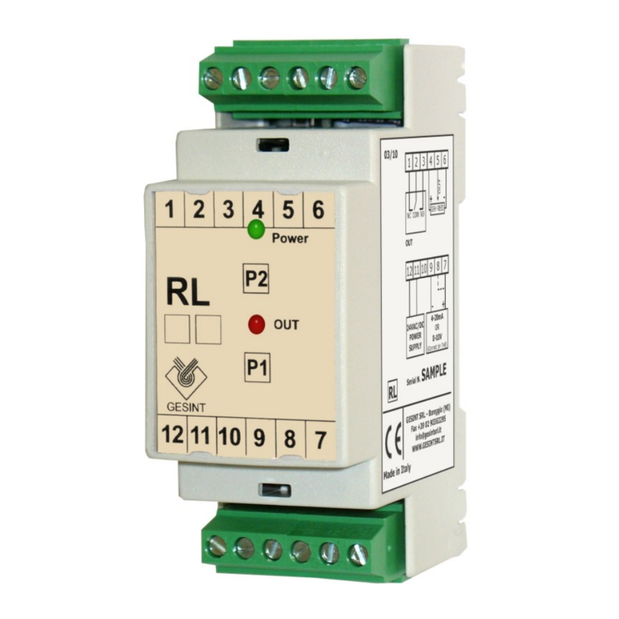
Introduction
RL transmitter convert the level measure from a GSH reed probe and a magnetic float in a 4-20mA or 0-10Vdc analog output signal. The output signal of the instruments is proportional to the distance between minimum and maximum point set during calibration.
The transmitter is supplied with 1 relay output that can be used as level threshold or alarm.
Digital calibrations and settings with 2 push buttons.
Electrical connection

It is recommended to use a connection cable of at least 0,5mmq section and a maximum length of 250mt. Connection cables must have separate run from power cables.
If the reed probe is installed upside-down, that is with the output connector near the minimum level, the connection polarity (PIN 4 and 6) must be inverted to obtain an output matching the level measured.
In order to use voltage output (0-10V) pin 7 and 8 must be connected together.
LED signalling
GREEN LED (Power):
- ON: transmitter is powered and working
- Fast blinking: programming mode
- Slow blinking: empty or invalid data in eeprom, transmitter need to be calibrated (both output and level)
RED LED (Out1 - Out2):
- ON: active level threshold
- Blinking: programming mode
0-100% level calibration
In order to access the 2 programming buttons, remove the front cover of the transmitter. Then connect a reference multimeter to the analogue output pins.
- Press P1 button for at least 3 seconds, until GREEN led start blinking, and RED leds blink alternatively.
- Set fluid level at minimum and wait until value on multimeter is stabilized. Then press and release P1 button.
- Now only one of the two RED leds is blinking. Set fluid level at maximum and wait until value on multimeter is stabilized. Then press and release P2 button.
- RED leds are now blinking together. Press both P1 and P2 and release them so that transmitter writes in memory the data acquired.
It is possible to acquire only of the two level settings, by pressing P1 button for minimum level or P2 button for maximum level and then confirm by pressing both P1 and P2.
Relay settings
It is possible to use the relay output as level threshold or alarm in case the reed probe is not sensing the magnetic float.
In order to access the 2 programming buttons, remove the front cover of the transmitter. Then connect a reference multimeter to the analogue output pins.
- Press P2 button for at least 3 seconds, until GREEN led start blinking, and RED leds blink alternatively.
-
- Use relay as level threshold: Set fluid at the desired level and wait until value on multimeter is stabilized. Now press and release P1.
- Use relay as alarm: press and release P2.
- To store acquired relay setting press and release both P1 and P2.
Is it possible to disable relay on the transmitter by executing only step 1) and 3).
4-20mA or 0-10V output calibration
During manufacturing and factory testing, the transmitter is calibrated for 4-20mA or 0-10V output using precise instruments. This calibration should be executed only if a different output type or range is needed.
During this calibration phase, relay output will be activated for diagnostic purpose. It is recommended to disconnect wires from pin 1, 2 and 3.
In order to access the 2 programming buttons, remove the front cover of the transmitter. Then connect a reference multimeter to the analogue output pins.
- While transmitter is powered off, keep pressed both P1 and P2 buttons and then power on.
- Keep both buttons pressed for at least 3 seconds, until GREEN led start blinking: now it's possible to release them.
- RED led below P1 is now on, indicating the output calibration corresponding to the minimum level.
- Press P2 for increase and P1 for decrease the output value, until you read on multimeter the needed value (ex. 0,0Vdc or 4,0mA).
- Now press both P1 and P2 and release them.
- OUT RED led is now on, indicating the output calibration corresponding to the maximum level.
- Press P2 for increase and P1 for decrease the output value, until you read on multimeter the needed value (ex. 10,0Vdc or 20,0mA).
- Now press both P1 and P2 and release them.
- Both RED led remain on for a few seconds while data are stored in the transmitter.
- Transmitter reset itself and start working.
Technical data
| Power supply: | 24VAC/DC switching |
| Power consumption: | 2VA / 1,8W max |
| Input signal: | Potentiometric |
| Reed probe voltage: | 5 Vdc |
| Analogue output: | 0/4-20mA or 0/2-10V |
| Output impedance: | Max 750Ω (mA) or Min 1KΩ (V) |
| Relay output: | 1 SPDT relay |
| Mechanical life: | min. 107 cycles |
| Electrical life: | N.O. @ 3A 250VAC: 5x10⁴ N.C. @ 2A 250VAC: 2x10⁵ |
| Contact rating: | 3A @ 30 VDC (resistive load) 3A @ 250 VAC (resistive load) |
| Programming: | 2 push buttons |
| Protection: | IP20 |
| Storage temperature: | from –30 to +80°C |
| Working temperature: | from –20 to +60°C |
| Relative humidity: | from 0 to 85%, no condensate |
| Installation: | 35 mm DIN rail |
| Electrical connection: | Removable terminal board |
| Dimensions: | 90(H) x 35(L) x 60(P) mm |
CE mark according to Directive 89/336/CEE, complies with the following harmonised regulations: EN50081-1, EN 50082-2, EN55022, EN61000-4-2, EN61000-4-3, EN61000-4-4, EN61000-4-5, EN61000-4-6, EN61000-4-11 and Low Voltage Directive 73/23/CEE and subsequent modifications.
Warranty
The warranty is valid for 12 months from purchase, and expires if instrument is improperly used or not correctly installed on system.
GESINT S.R.L.
Via Perosi, 5 - 20010 Bareggio (MI) - ITALY

Tel. +39-02-9014633 - +39-335-6282615
Fax +39-02-90362295
GESINT E-mail: info@gesintsrl.it
WWW.GESINTSRL.IT

Documents / Resources
References
Download manual
Here you can download full pdf version of manual, it may contain additional safety instructions, warranty information, FCC rules, etc.
Advertisement


Need help?
Do you have a question about the RL and is the answer not in the manual?
Questions and answers