
Related Manuals for Hobart Welding Products CHAMP 1435


Summary of Contents for Hobart Welding Products CHAMP 1435
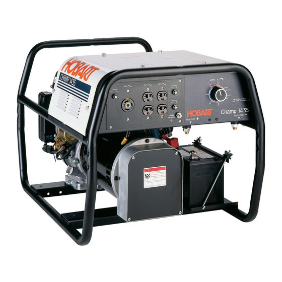
- Page 1 OM-490 495 370B January 2000 Processes Stick (SMAW) Welding Description Engine Driven Welding Generator CHAMP 1435 (Honda-Powered) Visit our website at www.HobartWelders.com...
- Page 2 From Hobart to You Thank you and congratulations on choosing Hobart. Now you can get the job done and get it done right. We know you don’t have time to do it any other way. This Owner’s Manual is designed to help you get the most out of your Hobart products.
-
Page 3: Table Of Contents
TABLE OF CONTENTS SECTION 1 – SAFETY PRECAUTIONS – READ BEFORE USING ......1-1. Symbol Usage . -
Page 5: Section 1 - Safety Precautions - Read Before Using
SECTION 1 – SAFETY PRECAUTIONS - READ BEFORE USING rom _nd_11/98 1-1. Symbol Usage Means Warning! Watch Out! There are possible hazards with this procedure! The possible hazards are shown in the adjoining symbols. This group of symbols means Warning! Watch Out! possible Y Marks a special safety message. -
Page 6: Engine Hazards
WELDING can cause fire or explo- HOT PARTS can cause severe burns. sion. D Allow cooling period before maintaining. Welding on closed containers, such as tanks, D Wear protective gloves and clothing when drums, or pipes, can cause them to blow up. Sparks working on a hot engine. -
Page 7: Additional Symbols For Installation, Operation, And Maintenance
BATTERY ACID can BURN SKIN and MOVING PARTS can cause injury. EYES. D Keep away from fans, belts, and rotors. D Do not tip battery. D Keep all doors, panels, covers, and guards D Replace damaged battery. closed and securely in place. D Flush eyes and skin immediately with water. -
Page 8: Principal Safety Standards
H.F. RADIATION can cause interference. ARC WELDING can cause interference. D High-frequency (H.F.) can interfere with radio D Electromagnetic energy can interfere with navigation, safety services, computers, and sensitive electronic equipment such as communications equipment. computers and computer-driven equipment D Have only qualified persons familiar with such as robots. -
Page 9: Section 1 - Consignes De Sécurité - Lire Avant Utilisation
SECTION 1 – CONSIGNES DE SÉCURITÉ – LIRE AVANT UTILISATION rom _nd_fre 11/98 1-1. Signification des symboles Signifie Mise en garde ! Soyez vigilant ! Cette procédure présente des risques de danger ! Ceux-ci sont identifiés par des symboles adjacents aux directives. Ce groupe de symboles signifie Mise en garde ! Soyez vigilant ! Il y a des Y Identifie un message de sécurité... -
Page 10: Dangers Existant En Relation Avec Le Moteur
LE SOUDAGE peut provoquer un in- DES PIÈCES CHAUDES peuvent cendie ou une explosion. provoquer des brûlures graves. D Prévoir une période de refroidissement avant d’effec- Le soudage effectué sur des conteneurs fermés tels que tuer des travaux d’entretien. des réservoirs, tambours ou des conduites peut provoquer D Porter des gants et des vêtements de protection pour leur éclatement. -
Page 11: Dangers Supplémentaires En Relation Avec L'installation, Le Fonctionnement Et La Maintenance
DES ORGANES MOBILES peuvent L’ACIDE DE LA BATTERIE peut pro- provoquer des blessures. voquer des brûlures dans les YEUX et sur la PEAU. D Ne pas approcher les mains des ventilateurs, cour- roies et autres pièces en mouvement. D Ne pas renverser la batterie. D Maintenir fermés et fixement en place les portes, D Remplacer une batterie endommagée. -
Page 12: Principales Normes De Sécurité
LE RAYONNEMENT HAUTE FRÉ- LE SOUDAGE À L’ARC risque de QUENCE (H.F.) risque de provoquer provoquer des interférences. des interférences. D L’énergie électromagnétique risque de provoquer des interférences pour l’équipement électronique D Le rayonnement haute fréquence (H.F.) peut sensible tel que les ordinateurs et l’équipement com- provoquer des interférences avec les équipements mandé... -
Page 13: Section 2 - Definitions
SECTION 2 – DEFINITIONS 2-1. Symbol Definitions Read Operator’s Engine Choke Amperes Volts Manual Engine Oil Fuel Battery (Engine) Engine Alternating Current Positive Negative Output (AC) Protective Earth Hours Seconds Time (Ground) Circuit Breaker Temperature SECTION 3 – SPECIFICATIONS 3-1. Weld, Power, and Engine Specifications Rated Maximum Welding... -
Page 14: Fuel Consumption
3-3. Fuel Consumption ST-802 121 3-4. Duty Cycle Duty cycle is the percentage of 10 minutes that unit can weld at rated load without overheating. Y Exceeding duty cycle can damage unit void Continuous Welding warranty. 100% Duty Cycle at 80 Amperes CC/DC 3 Minutes Welding 7 Minutes Resting 30% Duty Cycle at 140 Amperes CC/DC... -
Page 15: Auxiliary Power Curve
3-5. Auxiliary Power Curve The ac auxiliary power curves show the auxiliary power available in amperes at the receptacles. ST-802 129 3-6. Volt-Ampere Curves The volt-ampere curve shows the minimum and maximum voltage and amperage output capabilities of the welding generator. Curves of all other settings fall between the curves shown. -
Page 16: Section 4 - Installation
SECTION 4 – INSTALLATION 4-1. Installing Welding Generator Movement Airflow Clearance 18 in (460 mm) 18 in 18 in (460 mm) (460 mm) 18 in 18 in (460 mm) (460 mm) Location install1 1/97 – ST-802 100 / Ref. ST-151 556 / ST-158 936-A / S-0854 4-2. -
Page 17: Grounding Generator When Supplying Building Systems
4-3. Grounding Generator When Supplying Building Systems Equipment Grounding Terminal Grounding Cable GND/PE Use #10 AWG or larger insulated copper wire. Ground Device Y Ground generator to sys- tem earth ground if supply- ing power to a premises Use ground device as (home, shop, farm) wiring stated in electrical codes. -
Page 18: Connecting The Battery (Electric-Start Models Only)
4-5. Connecting the Battery (Electric-Start Models Only) Y Turn Engine Switch to Off (electric-start models only). Y Connect negative (–) cable last. – Tools Needed: 3/8, 1/2 in ST-802 100 / Ref. S-0756-D 4-6. Connecting to Weld Output Terminals Positive (+) Weld Output Terminal Negative (–) Weld Output Terminal... -
Page 19: Section 5 - Operating The Welding Generator
SECTION 5 – OPERATING THE WELDING GENERATOR 5-1. Controls (See Section 5-2) Recoil-Start Electric-Start 60 Hz ST-802 099 / ST-802 100 / 953T-5-4 OM-490 Page 15... -
Page 20: Description Of Controls (See Section 5-1)
5-2. Description Of Controls (See Section 5-1) lever to left if starting a cold engine. Move le- Welding Range Label Weld and auxiliary power output stops if ver to right if starting a warm engine. Use label to determine correct weld amper- generator overheats or engine speed is Starter Handle (Recoil-Start Models age based on electrode size, type, and mate-... -
Page 21: Section 6 - Operating Auxiliary Equipment
SECTION 6 – OPERATING AUXILIARY EQUIPMENT NOTE The welding generator provides power while welding and with the Current control in any position. However, under these conditions equipment connected to the welding generator may be subject to larger than normal voltage fluctuations. It is recommended that only lamps be powered under these conditions. -
Page 22: Optional Receptacle Panel Ratings
6-2. Optional Receptacle Panel Ratings NOTE Unless otherwise stated, the rating of duplex outlets is the combined load of all receptacles. Total power from generator NOT to exceed 3500 Watts (60 Hz) Protected Canada South South Receptacle USA-1 USA-2 USA-3 Europe Australia S.E. - Page 23 Total Power NOT 3500W 3500W 3500W 3500W 3500W 3500W 3500W 3500W 3500W to exceed Notes: 1. Each receptacle of the duplex can provide 15A/1800W. Do not parallel the two 120V duplex receptacles. 2. Do not parallel the two 120V circuits. 3.
-
Page 24: Section 7 - Maintenance
SECTION 7 – MAINTENANCE 7-1. Routine Maintenance Y Stop engine before maintaining. See Engine Manual and Maintenance Label. Ser- Recycle vice more often if used in severe conditions. engine fluids. To be done by Factory Authorized Service Agent. 20 h Check clean Check fluid levels. -
Page 25: Maintenance Label
NOTE Follow the storage procedure in the engine owner’s manual if the unit will not be used for an extended period. 7-2. Maintenance Label °C °F ENGINE MAINTENANCE 100 h +104 SG-SF/CC-CD 1.1 l (1.2 US qt, 1.94 lmp qt) Unleaded 86 + Octane 6.5 l (1.7 US Gal,... -
Page 26: Adjusting Engine Speed
7-4. Adjusting Engine Speed After tuning engine, check engine speeds. See table for proper no load speeds. If necessary, adjust speeds as follows: ± 1400 150 rpm Start engine and run until warm. Weld/Power Speed ± Adjustment 3720 50 rpm (60 Hz) Throttle Control Lever Adjustment Screw Move lever to Run (far left) position. -
Page 27: Section 8 - Troubleshooting
SECTION 8 – TROUBLESHOOTING 8-1. Troubleshooting A. Welding Trouble Remedy No weld output. Check Amperage control setting. Check weld connections. Be sure all equipment is disconnected from receptacles when starting unit. Have Factory Authorized Service Agent check brushes, slip rings, rotor, stator, reactor L2, output rectifier CR3, stabilizer L3, integrated rectifiers CR1 and CR2, and amperage control R1. - Page 28 C. Engine Trouble Remedy Engine will not crank (electric-start Reset ignition circuit breaker (see Section 7-3). models only). Check battery voltage. Check battery connections and tighten if necessary. Have Factory Authorized Service Agent check engine ignition circuit. Engine will not start. Check fuel level (see Section 4-4).
-
Page 29: Section 9 - Electrical Diagrams
SECTION 9 – ELECTRICAL DIAGRAMS Figure 9-1. Circuit Diagram For Welding Generator SC-495 297 OM-490 Page 25... - Page 30 SC-495 297 Figure 9-2. Wiring Diagram For Welding Generator (1 Of 3) OM-490 Page 26...
- Page 31 SC-495 297 Figure 9-3. Wiring Diagram For Welding Generator (2 Of 3) OM-490 Page 27...
- Page 32 SC-495 297 Figure 9-4. Wiring Diagram For Welding Generator (3 Of 3) OM-490 Page 28...
-
Page 33: Section 10 - Auxiliary Power Guidelines
SECTION 10 – AUXILIARY POWER GUIDELINES 10-1. Selecting Equipment Auxiliary Power Receptacles – Neutral Bonded To Frame 3-Prong Plug From Case Grounded Equipment 2-Prong Plug From Double Insulated Equipment Be sure equipment has this symbol and/or wording. aux_pwr 2/99 – Ref. ST-159 730 / ST-800 577 10-2. - Page 34 10-3. Grounding When Supplying Building Systems Equipment Grounding Terminal Grounding Cable GND/PE Use #10 AWG or larger insulated copper wire. Ground Device Y Ground generator to system earth ground if supplying power to a premises (home, shop, farm) wiring system. Use ground device as stated in electrical codes.
- Page 35 10-5. Approximate Power Requirements For Industrial Motors Industrial Motors Rating Starting Watts Running Watts Split Phase 1/8 HP 1/6 HP 1225 1/4 HP 1600 1/3 HP 2100 1/2 HP 3175 Capacitor Start-Induction Run 1/3 HP 2020 1/2 HP 3075 3/4 HP 4500 1400 1 HP...
- Page 36 10-7. Approximate Power Requirements For Contractor Equipment Contractor Rating Starting Watts Running Watts Hand Drill 1/4 in 3/8 in 1/2 in Circular Saw 6-1/2 in 7-1/4 in 8-1/4 in 1400 1400 Table Saw 9 in 4500 1500 10 in 6300 1800 Band Saw 14 in...
- Page 37 10-8. Power Required To Start Motor Motor Start Code AC MOTOR Running Amperage VOLTS AMPS Motor HP CODE Motor Voltage PHASE To find starting amperage: Step 1: Find code and use table to find kVA/HP. If code is not listed, multiply running amperage by six to find starting amperage.
- Page 38 10-10. Typical Connections To Supply Standby Power Power Company Service Meter Main and Branch Overcurrent Protection Double-Pole, Double-Throw Transfer Switch Obtain and install correct switch. Customer-supplied equipment is required if Switch rating must be same as or generator is to supply standby power during greater than the branch overcurrent emergencies or power outages.
- Page 39 10-11. Selecting Extension Cord (Use Shortest Cord Possible) Cord Lengths for 120 Volt Loads Y If unit does not have GFCI receptacles, use GFCI-protected extension cord. Maximum Allowable Cord Length in ft (m) for Conductor Size (AWG)* Current Load (Watts) (Amperes) 350 (106) 225 (68)
-
Page 40: Section 11 - Stick Welding (Smaw) Guidelines
SECTION 11 – STICK WELDING (SMAW) GUIDELINES 11-1. Stick Welding Procedure Y Weld current starts when electrode touches work- piece. Y Weld current can damage electronic parts in vehicles. Disconnect both battery cables before welding on a vehicle. Place work clamp as close to the weld as possible. - Page 41 11-2. Electrode and Amperage Selection Chart 3/32 6010 5/32 & 3/16 6011 7/32 6010 DEEP MIN. PREP, ROUGH 1/16 HIGH SPATTER 6011 DEEP 5/64 6013 EP,EN GENERAL 3/32 SMOOTH, EASY, 6013 7014 EP,EN FAST 5/32 3/16 LOW HYDROGEN, 7018 STRONG 7/32 FLAT SMOOTH, EASY,...
- Page 42 11-5. Positioning Electrode Holder ° ° ° ° End View of Work Angle Side View of Electrode Angle GROOVE WELDS ° ° ° ° End View of Work Angle Side View of Electrode Angle FILLET WELDS S-0060 11-6. Poor Weld Bead Characteristics Large Spatter Deposits Rough, Uneven Bead Slight Crater During Welding...
- Page 43 11-8. Conditions That Affect Weld Bead Shape NOTE Weld bead shape is affected by electrode angle, arc length, travel speed, and thickness of base metal. Correct Angle ° - ° Angle Too Large Angle Too Small Drag ELECTRODE ANGLE Spatter Normal Too Long Too Short...
- Page 44 11-10. Butt Joints Tack Welds Prevent edges of joint from drawing together ahead of electrode by tack welding the materials in position be- fore final weld. Square Groove Weld Good for materials up to 3/16 in (5 mm) thick. Single V-Groove Weld °...
- Page 45 11-13. Weld Test Vise Weld Joint Hammer Strike weld joint in direction shown. A good weld bends over but does not break. 2 To 3 in (51-76 mm) 2 To 3 in (51-76 mm) 1/4 in (6.4 mm) S-0057-B 11-14. Troubleshooting – Porosity Porosity –...
- Page 46 11-16. Troubleshooting – Incomplete Fusion Incomplete Fusion – failure of weld metal to fuse completely with base metal or a preceeding weld bead. Possible Causes Corrective Actions Insufficient heat input. Increase amperage. Select larger electrode and increase amperage. Improper welding technique. Place stringer bead in proper location(s) at joint during welding.
- Page 47 11-19. Troubleshooting – Burn-Through Burn-Through – weld metal melting completely through base metal resulting in holes where no metal remains. Possible Causes Corrective Actions Excessive heat input. Select lower amperage. Use smaller electrode. Increase and/or maintain steady travel speed. 11-20. Troubleshooting – Waviness Of Bead Waviness Of Bead –...
-
Page 48: Section 12 - Parts List
SECTION 12 – PARTS LIST Hardware is common and not available unless listed. ST-802 153-A Figure 12-1. Main Assembly OM-490 Page 44... - Page 49 Item Dia. Part Mkgs. Description Quantity Figure 12-1. Main Assembly ....+495 247 TOP, control box (specify color) ........
- Page 50 Hardware is common and not available unless listed. USA-1 EUROPE S.AMERICA AUSTRALIA S. AFRICA S.E. ASIA USA-3 USA-2 CANADA (CSA) Ref. ST-802 124 / H-495 290 / H-495 283 Figure 12-2. Auxiliary Power Panel OM-490 Page 46...
- Page 51 Item Part Description Quantity Figure 12-2. Auxiliary Power Panel ......PANEL, aux power assembly (USA-1) .
- Page 52 Notes OM-490 Page 48...
- Page 53 Notes OM-490 Page 49...
- Page 54 Notes OM-490 Page 50...
- Page 55 Effective October 1, 1999 5/3/1 WARRANTY applies to all Handler 135 and 175 models, Airforce 250, 250A, and 375 Warranty Questions? models, and Champion 10,000 models.This warranty also applies to the Beta-Mig 1800, Champ Call 1435, 2060, 8500 models, Ironman 250, Stickmate models, Tigmate models, and HSW-15 and 1-877-HOBART1 HSW-25 spot welder models effective with Serial No.
-
Page 56: Options And Accessories
Call 1-877-Hobart1 Contact the Delivering Carrier for: File a claim for loss or damage during shipment. For assistance in filing or settling claims, contact your distributor and/or equipment manufacturer’s Transportation Department. PRINTED IN USA 2000 Hobart Welding Products. 1/00...
Need help?
Do you have a question about the CHAMP 1435 and is the answer not in the manual?
Questions and answers