Subscribe to Our Youtube Channel
Summary of Contents for EONE SENTRY Protect
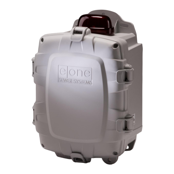
- Page 1 SENTRY Protect SIMPLEX PANEL Installation and Operation Manual For Wireless and Explosion Proof Pumps Environment One Corporation...
-
Page 2: Table Of Contents
Table of Contents Overview ..................................3 Wiring Instructions ................................4 Alarm Dry Contacts ..............................4 Switch Over Dry Contacts – to be used with an E/One Remote Sentry (optional) ..........4 Startup and System Initialization ............................ 4 DIP Switch ................................4 User Interface Membrane ............................... -
Page 3: Overview
Alarm Dry Contacts – Normally Open (Requires alarm board to have power) Once the Sentry Protect Panel is properly installed by mounting and wiring the panel per the instructions on the enclosure door, it is ready to operate. No further setup is required. -
Page 4: Wiring Instructions
The Sentry Protect panel is equipped with one set of switch over dry contacts. If power is applied to the panel these contacts respond just as the Alarm Dry Contacts described above. When connected to an E/One Remote Sentry, that device will respond with an audible and visual alarm in conjunction with above indicated alarm conditions. -
Page 5: User Interface Membrane
4 User Interface Membrane The Sentry Protect panel includes a user interface to indicate the various operating and trouble conditions (see Figure 1). Three system status LED’s indicate the current pump status and indicate the various operating conditions. These are ‘Normal’, ‘Pump Running’... -
Page 6: Manual Run Operation
2. When the boot-up sequence is complete and the voltage has settled to an acceptable level, the Alarm Lamp will turn off and the green Normal LED will light and the panel is in its normal operating mode and ready for operation.. -
Page 7: Overvoltage Operation
starting (if the pump is off), or is shut off (if the pump is running) until the voltage returns to within the desired range of operation, typically 10% of the nominal nameplate rating. When in the Brownout Protection mode, the panel will disable power to the pump, whether the motor is running or not, and the amber Brownout LED will light. -
Page 8: Alarm Circuit Protection
6.6 Alarm Circuit Protection Each circuit board contains circuitry to help limit any permanent damage due to a mis-wire or short within the alarm pressure switch circuit. While this does not guarantee protection in all cases, if activated, this feature acts as a resettable fuse and will temporarily open the circuit to help prevent damage to the circuit board itself. -
Page 9: Trouble Shooting
8 Trouble Shooting The following chart is meant to address some common panel related issues. For more detailed information or pump specific troubleshooting, please refer to the appropriate Service Manual or contact E/One service personnel. 8.1 Troubleshooting Chart Test Fault Symptom Possible Cause •... - Page 10 Test Fault Symptom Possible Cause • Verify wires are connected as per decal inside panel cover Panel mis-wired, faulty • Manual run not Manual run does not manual run button, faulty working make pump run PCB, trouble condition present • Verify wires are connected as per decal inside panel cover Flashing Alarm Lamp Brown wires from PCB are •...
-
Page 11: Appendix
9 Appendix 9.1 Wiring Diagrams 9.1.1 240V, 2-leg basic panel wiring (for US installations) NA0269P11 REV C 7/5/2023... -
Page 12: 240V, 2-Leg Optional Panel Wiring (For Us Installations)
9.1.2 240V, 2-leg optional panel wiring (for US installations) NA0269P11 REV C 7/5/2023... -
Page 13: 240V, 1-Leg Basic Panel Wiring (For Non-Us Installations)
9.1.3 240V, 1-leg basic panel wiring (for non-US installations) NA0269P11 REV C 7/5/2023... -
Page 14: 240V, 1-Leg With Optional Generator Receptacle, Manual Transfer Switch (For Non-Us Installations)
9.1.4 240V, 1-leg with optional generator receptacle, manual transfer switch (for non-US installations) NA0269P11 REV C 7/5/2023... - Page 15 A Precision Castparts Company Environment One Corporation 2773 Balltown Road Niskayuna, New York 12309–1090 Voice: (01) 518.346.6161 Fax: 518.346.6188 www.eone.com NA0269P11 REV C 7/5/2023...


Need help?
Do you have a question about the SENTRY Protect and is the answer not in the manual?
Questions and answers