Advertisement
Advertisement
Table of Contents

Related Manuals for ZEEWEII DSO3D12


Summary of Contents for ZEEWEII DSO3D12
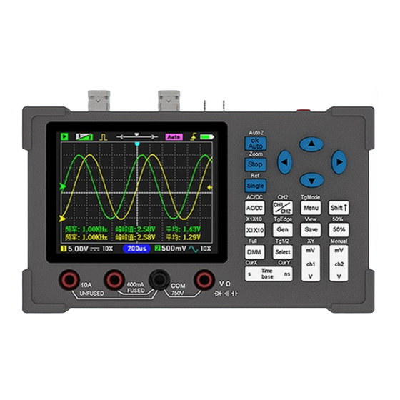
- Page 1 DSO3D12 DIGITAL OSCILLOSCOPE User’s Manual Designed by ZEEWEII...
- Page 2 ① Green is the running state; Flashing cyan for waiting to trigger; Red is stopped. ② Channel priority: Yellow 1 indicates that CH1 has high priority, and the CH1 waveform can be moved up or down. ③ Yellow: Turn on the signal generator output; Gray: Turns off the output. ④...
-
Page 3: Buttons Function
Buttons Function 1. Default function (function on button) 1. When the menu opens, as the OK button. Auto 2. as an "Auto" button Stop Run / Stop Single Single trigger AC/DC Switch DC/AC coupling(CH1) CH1/CH2 Change the CH1/CH2 priority Menu Open/close the menu Shift⬆... -
Page 4: Safety Precautions
Quick centering (CH2) Full The multimeter is displayed in full screen Tg1/2 Switch trigger source: Ch1 / CH2 Note: CH1 cannot be turned off, CH2 can be turned on or off. When two channels are not required, CH2 should be turned off for higher sample rates and reduced power consumption. -
Page 5: Quick Start Instructions
2 Quick start instructions 2.1 Power Press and hold the power button on/off. When the battery is dead, use the USB cable to connect to the 5V adapter for charging, and the charging current is about 700mA. It is best to use a computer or mobile phone for charging. -
Page 6: Probe Calibration
multimeter function table, select the function and press the [OK] key. If you want to measure the current, insert the red pen into the current hole, and pay attention to the "series" of the meter pen and the power line. When charging: Multimeter is not supported, and the oscilloscope cannot measure high voltage or non-isolated circuits. - Page 7 is displayed stably at a suitable position on the screen. 4. Use a screwdriver to rotate the adjustable capacitor on the probe until you get the waveform in the middle of the figure below. The left and right waveforms below are references for incorrect calibration.
-
Page 8: Vertical System
first switch the probe to the 10X position before connecting the high voltage signal, otherwise the high voltage may break down the internal circuit of the oscilloscope. 3.4.3 High bandwidth Because the 1X probe has a large input capacitance, the bandwidth of the probe 1X is usually within 5MHz, so please use the 10X position when the measured signal bandwidth is greater than 5M. -
Page 9: Horizontal System
5 Horizontal system 5.1 Time base The time base refers to the time represented by each grid in the horizontal direction on the oscilloscope screen. There are 12 grids in the horizontal direction of the oscilloscope. The sampling time that can be observed on the screen = " time base" * 12.The user can estimate the signal period by observing how many grids a waveform period occupies. -
Page 10: Trigger Level
meets the pre-set conditions. This action of capturing the waveform according to the conditions is the trigger. What does trigger do? 1. Trigger can stabilize the waveform on the screen. 2. Capture the segment of the waveform you want to observe. The trigger supported by the oscilloscope is edge trigger, including rising edge trigger and falling edge trigger. -
Page 11: Single Trigger
7 Operation Guide 7.1 50% The role of 50% is to quickly return to the center, including zero point offset, trigger position, trigger level will quickly return to the middle position with one button, operation method: directly click "50%". 7.2 Single trigger Suitable for sporadic single pulse capture. - Page 12 7.5 Signal generator Signal generator Click the " Gen " button button to call up the window of the signal generator, of the signal generator, The signal amplitude is 2.5V, the maximum frequency of the sine wave is amplitude is 2.5V, the maximum frequency of the sine wave is 5M, and the other M, and the other waves are 1M.
-
Page 13: Menu Introduction
dashed lines. The vertical (voltage) cursor can only measure one channel, and whichever channel has the highest priority, measure the voltage of which channel. 8 Menu introduction 8.1 Channel The channel menu includes two options, "Coupling" and "Probe". The coupling can be set "DC coupling" and "AC coupling". DC coupling passes the signal directly. - Page 14 For “Normal” mode, The oscilloscope will not refresh the display until there is a waveform trigger. Therefore, in this mode, the screen waveform may not refresh or there is no waveform. It is suitable for measuring discontinuous waveforms and requires users to adjust the trigger level in advance. Trigger type includes rising and falling edges.
- Page 15 2. You can choose whether to turn on sound or not. 3. Choice of language: Chinese or English. 4. Keep this menu open, and long press "s" to switch the background color of the measurement item. Parameters Model DSO3D12 Coupling AC/DC Channels AUTO Support Screen size 3.2inch...
- Page 16 20 seconds after waking up, it will automatically go to sleep. Note that due to the size of the voice, speech rate, accent, etc.,we cannot guarantee the accuracy of recognition. Wake-up command: "Hello, ZEEWEII" (Pronounced "Hello,see wave") or "Hello,mini scope". Command words...
- Page 17 channel two on off Turn on/off CH2 T B second It is equivalent to pressing the “s” key once nano second It is equivalent to pressing the “ns” key once M V one It is equivalent to pressing the “mV(ch1)” key once V one It is equivalent to pressing the “V(ch1)”...
- Page 18 Answer: First, set the coupling to "DC", and adjust the probe to the 10X position (the oscilloscope menu should also be set to the same 10X as the probe). Connect the probe to the power output terminal, and then click the [Auto] key. Pay attention to the "Mean"...
Need help?
Do you have a question about the DSO3D12 and is the answer not in the manual?
Questions and answers