
Related Manuals for Clopay VERTISTACK CLEAR DOOR


Summary of Contents for Clopay VERTISTACK CLEAR DOOR
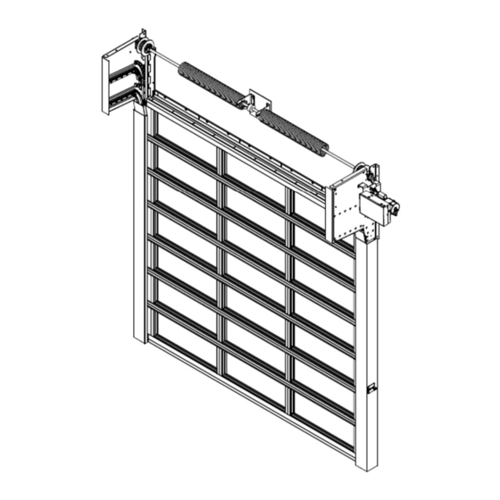
- Page 1 VERTISTACK™ CLEAR DOOR INSTALLATION & MAINTENANCE COMMERCIAL HOTLINE • 1-800-277-2576 Installation Instruction Video Model: Serial No. (Provided on label on interior door surface) Size:...
- Page 2 If you should require any assistance or additional information, please call the hotline number on the cover of this manual. Thank you again for choosing Clopay Corporation products! Attention! This product is intended for Commercial applications only. Installation of this product in Residential applications will void the VertiStack warranty.
-
Page 3: Table Of Contents
TABLE OF CONTENTS TABLE OF CONTENTS ............................3 Things to Know Before You Begin ................7 Tools Needed ......................... 8 Freight Receiving......................9 Checking and Preparing the Opening ................ 10 Installing the Right-Hand Wall Angle, Track, and Brackets ........10 Installing the Left-Hand Wall Angle, Track, and Brackets ........15 Installing Track Rollers, Strap and Loading Bottom Section ........ - Page 4 MEAN “WARNING” AND A SITUATION WHERE NOTE – THESE SYMBOLS: DEATH OR SERIOUS INJURY COULD RESULT IF WARNING INSTRUCTIONS ARE NOT CAREFULLY FOLLOWED. TO PROTECT YOURSELF FROM INJURY, CAREFULLY READ AND STRICTLY FOLLOW ALL SAFETY INFORMATION AND WARNINGS. FOR CERTIFIED INSTALLERS: ALL INSTALLATION AND MAINTENANCE INSTRUCTIONS FOR THIS PRODUCT MUST BE PERFORMED BY A CERTIFIED INSTALLER, WHICH IS DEFINED AS A DEALER THAT HAS SUCCESSFULLY COMPLETED ALL REQUIRED VERTISTACK TRAINING PROVIDED BY THE...
- Page 5 FOR USERS: DO NOT OPERATE IF THE DOOR’S TEMPERATURE IS 32°F (0°C) OR BELOW. DO NOT OPERATE IF AN OPERATING ISSUE ARISES. IMMEDIATELY STOP USE AND CONTACT YOUR CERTIFIED INSTALLER. NEVER ATTEMPT REPAIR OR MANUAL OPERATION. TO ENSURE SAFETY DEVICES AND PROCESSES ARE FULLY FUNCTIONAL, ALL USERS MUST OPERATE THIS DOOR USING THE MOTOR OR OPERATOR SET TO “MOMENTARY CONTACT”...
- Page 6 The manufacturer disclaims all – and shall not be responsible for any – all liability for any installation which is not in compliance with applicable state, county, or local building codes. Releasing a VertiStack door order requires certification from the dealer that all individual(s) handling or installing the VertiStack door product have successfully completed all “VertiStack Door Installation Training”...
-
Page 7: Things To Know Before You Begin
Things to Know Before You Begin Before Starting Installation: MUST HAVE COMPLETED MANUFACTURER’S VERTISTACK DOOR INSTALLATION Check the opening size and verify that the door is TRANING CERTIFIED BEFORE the proper size for the opening. As standard, door INSTALLATION IS ATTEMPTED. -
Page 8: Tools Needed
Tools Needed Laser Level “C” Clamps or Locking Pliers Hammer Winding Bars (Torsion Only) Screwdriver Tape Measure Level Socket wrench kit Pliers Drill and 1/4" [6 mm], 3/16" [5 mm] and 3/8" [10 mm] bits ... -
Page 9: Freight Receiving
Freight Receiving If the installation proceeds without following the instructions below, neither the carrier nor the manufacturer will assume responsibility for replacing any damaged material, installation issues that arise, or any personal injury or property damage that may result. STEP1 – UPON DELIVERY, CHECK CONDITION OF COMPONENTS FOR DAMAGE. ... -
Page 10: Checking And Preparing The Opening
If the delivery is incomplete: 1. Make note on delivery receipt. 2. Note should be verified by driver’s signature. 3. Notify both carrier and manufacturer. Checking and Preparing the Opening 1. Check the floor to ensure it is level. If necessary, shim the area where the wall angle and track will sit on the floor. - Page 11 Figure 2 - BOTTOM OF RIGHT-HAND LOWER WALL ANGLE ASSEMBLY 6. Disassemble track from the right-hand lower wall angle and set track aside. (Note: The lower wall angle cannot be installed properly without removing the track first). 7. Place lower wall angle on the floor (shim if needed) against the jamb, holding the small flange of the wall angle flush with the inside of the jamb.
- Page 12 13. Fasten the upper wall angle assembly to the wall using the supplied fasteners. Mark and predrill holes if desired. 14. Attach sensor to upper wall angle, referring to Figure 4 for placement: Locate sensor mounting studs. Ensure lens on sensor is pointing OUTWARDS from inside of wall angle. Attach sensor to studs and install nuts to fasten sensor.
- Page 13 Figure 6 - WIRING HARNESS PATH 15. Locate the right-hand bracket assembly, see figure below. Attach the bracket assembly to the upper wall angle assembly using the 3/8 x 1” [9 mm x 25 mm] carriage bolts, washers, and nuts provided in the hardware box.
- Page 14 Figure 8 - RIGHT HAND BRACKET ASSEMBLY WITH WALL FASTENERS 20. Attach the lower track piece, removed in step 6, to the wall angle using 1/4" x 5/8" [6 mm x 16 mm] track bolts and nuts. Making sure to also install the additional track bolt in the top of the track through the top wall angle.
-
Page 15: Installing The Left-Hand Wall Angle, Track, And Brackets
Installing the Left-Hand Wall Angle, Track, and Brackets Figure 10 – Header Seal Cross Member 21. Locate the header seal cross member. This will be used to set the spacing of the left-hand lower wall angle. 22. Measure the length of the header seal cross member from notched face to notched face and confirm it equals the opening width dimension listed on the shop sheet. -
Page 16: Installing Track Rollers, Strap And Loading Bottom Section
26. Plumb the left-hand wall angle against the wall. The short flange of the wall angle should be flush with the jamb or on the mark placed on the jamb if the opening width was less than stated on the shop drawings, see step 2. - Page 17 Figure 13 - AXLE SPACER 33. Remove the cotter pin in order to remove the strap pin shown in Figure 14. 34. Attach the straps to the bottom section. Place the loop of the strap, without tag and with the fold over side facing the door, in the bottom insert assembly.
-
Page 18: Installing The Shaft Assembly, Spools, And Straps
35. Place the bottom section into the opening down through the vertical track, as seen in Figure 16, and place section on floor. Figure 16 - RIGHT-HAND TRACK AND TRACK ROLLER SPACING 36. If the floor is out of level, shim the bottom section to make it level at this time. Installing the Shaft assembly, Spools, and Straps 37. - Page 19 38. Establish a “level line” across the header located at the center of the shaft bearings in the left and right-hand bracket assemblies. 39. Establish a “centerline” on the header between the bracket assemblies. 40. Fasten the spring anchor bracket to the spring pad using the provided red-color fasteners. Figure 17 –...
- Page 20 Figure 18 – SHAFT ASSEMBLY 48. To attach the strap to the spool, feed the strap up behind and over the top of the spool and into the strap slot, with the tag side facing in toward the spool, thread the strap bolt through the spool flanges and securely tighten the strap bolt.
-
Page 21: Installing The Motor Operator
WARNING The push button switch must be set to “momentary pressure” and installed within 3 feet of the door with a clear visual line of sight of the door. The individual operating the door must ensure there are no other people or objects within a three (3) foot radius of the door while in operation and must watch the door at all times. -
Page 22: Installing The Header Seal Cross Member
56. Fasten the motor mounting bracket to the bracket plate using the provided 3/8 x 1” [10 mm x 25 mm] carriage bolts. Then, if required, fasten the motor bracket to the wall using the appropriate hardware for the wall construction. 57. -
Page 23: Installing Track Rollers And Loading Intermediate Section
Figure 22- SENSOR WIRING PLACMENT DIAGRAM (RIGHT-HAND MOUNTED OPERATOR SHOWN) Installing Track Rollers and Loading Intermediate Section 63. Install the black track rollers in all sections, making sure to slide an axle spacer on each of the track roller axles before inserting the track rollers into the end stiles of each section. Figure 23–... -
Page 24: Installing Lintel Seal Plate To The Top Section
Figure 24– REMOVABLE TRACK Installing Lintel Seal Plate to the Top Section 67. The top section is taller than the intermediate section and does not have rocker arm assemblies. See Figure 25. Figure 25– TOP SECTION 68. Place the top section on sawhorses or other supports. 69. -
Page 25: Loading The Top And Remaining Intermediate Sections
Figure 26– LINTEL SEAL FASTENED TO TOP SECTION 72. Adjustments may be needed to locate the lintel seal plate so that it properly seals with the header seal cross member. Use the slots in the plate to move it in or out and then tighten the fasteners to hold in place. -
Page 26: Installing The Lock
Fasten the bracket stop plate, using the supplied track bolts, to the back of both left and right-hand bracket assemblies. The bracket stop plate retains the sections in the magazine and must be installed. 74. With all sections installed and properly set, confirm the lintel seal (top section) is in contact with the header seal cross member (wall header). - Page 27 Figure 29 – LOCKING SETUP (Right Hand Guide – Unlocked State) Figure 30 - LOCK HANDLE (Right Hand Guide – Unlocked State)
-
Page 28: Installing Sensing Devices
Installing Sensing Devices Note: See Operator Manual for wiring information. 81. Sensing Edge: If the sensing edge option was selected, see separately supplied sensing edge installation instructions and proceed to Step 88. 82. Light Curtains: Two sizes for the light curtains are shown, a 3’ and 6’ option. Review your order to make sure you have the correct size light curtain, otherwise the door may be inoperable. -
Page 29: Winding The Spring
83. Photo Eyes: Photo eyes are installed on the lower portion of the lower wall angles. Attach the guide mounting bracket to the lower wall angle. Orient the photo eye and secure to guide mounted bracket as shown in Error! Reference source not found. -
Page 30: Setting The Operator Limits & Torque Sensor
depth of the holes in the winding cone. Keep a firm grip on the winding bars at all times. Use a sturdy ladder and stand to the side of the winding bars. 84. Draw a straight line across the spring. This will be used as a reference to indicate the number of turns on the spring as turns are added. -
Page 31: Installing The Jamb Seal
89. Set the upper limit on the operator. 90. Set the torque sensor on the operator (detailed instructions found in the Operator’s Manual). a. The initial goal is to adjust the torque sensor until the door fails to close. If the door still closes, adjust the sensor by ½... - Page 32 Figure 35 – GUIDE COVER ATTACHMENT Figure 36– TRACK COVER...
-
Page 33: Installing The Hood (If Equipped)
Installing the Hood (If Equipped) 100. Install the center hood support first, if supplied. Attach the center hood support to the spring pad in the center of the opening, ensuring the top of support bracket is flush with top of both left and right- hand brackets. -
Page 34: Chain Cover (Option)
Installing Chain Cover (If Equipped) 102. If the chain cover option is selected, attach the chain cover around the motor mounting bracket, chain and sprocket. Side mount configuration: Align the top holes of the chain cover with the top of the motor bracket and align the slotted holes with the holes in the bracket. -
Page 35: Maintenance
Figure 41 – TOP MOUNTING CHAIN COVER OPTION Maintenance WARNING Do not attempt to adjust door components. Call an authorized representative of the manufacturer or professional door repair service promptly. Attempting to adjust door components may cause the doors sections to suddenly release with force and risk of death or severe injury, including pinch, crush or amputation-type injuries. - Page 36 © 2023 Clopay Corporation 4152750, DN 105828-Rev04, 06/16/2023...
Need help?
Do you have a question about the VERTISTACK CLEAR DOOR and is the answer not in the manual?
Questions and answers