
Related Manuals for ELKHART BRASS EXM2 BoaX2 2000


Summary of Contents for ELKHART BRASS EXM2 BoaX2 2000
- Page 1 Powered by EXM2 Model 7451X2 Monitor Installation, Operating, & Maintenance Instructions 98638000 REV-A +1 574-295-8330 www.elkhartbrass.com...
-
Page 2: Table Of Contents
CONTENTS PRODUCT SAFETY INFORMATION ..............3 MONITOR CALLOUT DRAWING . -
Page 3: Product Safety Information
PRODUCT SAFETY INFORMATION • All personnel who may be expected to use this equipment must be thoroughly trained in its safe and proper use. • Before flowing water from this device, check that all personnel (fire service and civilian) are out of the stream path. -
Page 4: Monitor Callout Drawing
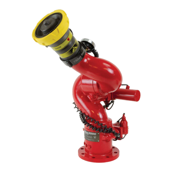
EXM2 MONITOR FEATURE CALLOUTS X-Stream Series Electronically Actuated Nozzle Discharge Pressure Gauge 3.5” NHT Discharge EXM2 Control Module Fully Vaned Cast Aluminum Waterway Sealed High-Torque Gearmotor 4”-150# Flange Base BoaX2 2000 Monitor... -
Page 5: System Components
Refer to the Operating Instructions section for more on setting Keep-Out Zones. A left and right Keep-Out Zone are factory set at Elkhart Brass so that the monitor discharge elbow and stream shaper do not contact the horizontal motor and sensor geometry. If the monitor is recalibrated or if these Keep-Out Zones are removed, new Keep-Out Zones or Travel Limits must be set to prevent potential interferences between these parts. - Page 6 12VDC nozzle should be used, or nozzle control may not function properly. ELKHART BRASS Fire Fighting Equipment THIS DRAWING CONTAINS INFORMATION THAT IS PROPRIETARY TO ELKHART BRASS MFG CO., INC. AND MAY NOT BE USED TO PRODUCE ANY PARTS, ASSEMBLIES OR PRODUCTS DESCRIBED HEREIN WITHOUT EXPRESS WRITTEN PERMISSION...
-
Page 7: Control
CONTROL Joystick Controller – 7030X2 The Joystick Controller can be mounted inside the apparatus cab to control all monitor functions, including oscillation, stow and deploy. The monitor direction (both vertical and horizontal movement) is changed by moving the joystick in the desired direction of travel. The up-down and left-right motions can be operated simultaneously with pressure sensitive speed, moving the monitor faster or slower depending on how far the joystick is pushed and pulled. -
Page 8: Monitor & Valve Accessories
MONITOR & VALVE ACCESSORIES Position Feedback Display – 7051X2 All EXM2 monitors come with Absolute Position Feedback sensors. These sensors provide constant feedback to the monitors’ processor even when the monitor is moved via manual override. This information is then transmitted to the Position Feedback Display. -
Page 9: Installation Step 1: Mount And Wire All System Components
Termination Points When using CAN lines for communication there must be 2 termination points within the system. The monitor should be considered one of these terminating points and located at one end of main CAN line. Termination points are explained further in the Configuration section (installation step 2). What is important at this time is that in order to maximize the efficiency of communication in your CAN network, you must terminate the component located at the opposite end of the main CAN line. - Page 10 Stow Output: The EXM2 monitor provides one electrical output to which an OEM can connect to in order to enable/disable truck operations based on whether an EXM2 monitor is stowed or not stowed. This could be used, for example, for a truck that has an aerial or other movable object that may hit the monitor if moved when the monitor is not stowed.
- Page 11 Connecting an OEM supplied proximity sensor to the wire from position 4 will provide conditional extended travel functionality via a ground or open circuit (see Operating Instructions). Connecting the proximity sensor wire from position 4 to a ground will provide an always enabled extended travel.
- Page 12 Harness E – EXM2 Extension harness (sold separately) Harness F – P/N 24196000 Splitter (sold separately) Harness G – P/N 24197000 CAN Termination Plug (sold separately) Harness H – P/N 37561000 Docking Station Pigtail included with EXM2 Hand Held pkg Harness J - P/N37551000 Gateway Pigtail included with EXM2 Hand Held pkg Harness K - P/N 37252000 Monitor CAN J1939 Pigtail Harness L - P/N 37571000 Input Controller CAN Pigtail...
- Page 13 EXM2 Wiring Connections (Shown with all Elkhart Brass Provided harnessing) CAN Splitter CAN Splitter CAN Splitter Terminating Resister 7051X2 EXM2 Position 7010X2 EXM2 Panel Mount E14X/E16X EXM2 Monitor Feedback Module EXM2 Gateway Actuated Valve 7030X2 EXM2 Joystick Controller (Both Factory Set as Primary)
- Page 14 Handheld Controller, Gateway and Docking Station Docking Station • Using the Docking Station template located at www.elkhartbrass.com, drill 6 #7(0.201" 5.1mm) drill holes as shown through the panel. • Mount the Docking Station with six (6) 10-24 screws using blue Loctite 242 or equivalent.
- Page 15 Joystick Controller • Using the Joystick Controller template located at www.elkhartbrass.com, drill all holes as shown through the panel. • Mount the Joystick Controller using 4 3/8" fasteners secured with blue Loctite 242 or equivalent. • Connect plug 2 to the appropriate CAN line. Joystick Plug Information •...
- Page 16 Position Feedback Display • Using the Position Display template located at www.elkhartbrass.com, drill the two 11/64" holes as shown through the panel intended for mounting the display. • Mount the Position Feedback Display using two (2) 6-32 x ½" fasteners secured with blue Loctite 242 or equivalent.
- Page 17 Valve Plug 1 Valve Plug Actuator Plug E14X (E16X for EB6D) Nozzles • Ensure there is a gasket inside the nozzle swivel. • Hand tighten the nozzle onto the monitor discharge. • Loosen the swivel to reposition the nozzle with the electric actuator on top as shown. •...
-
Page 18: Installation Step 2: Configure The Exm System
• Group number used for multiple monitors on system • Valve ID change for multiple valves • CAN address for special system of not using Elkhart Brass controls • Valve closure before stowing monitor need to be turned off If the system requires configuration, please refer to the EXM2 System Configuration Manual (P/N 98612001) for configuration instructions. - Page 19 Caution: There are no vertical or horizontal travel limits when in Setup Mode. MOVE THE MONITOR WITH CAUTION WHILE IN THIS MODE. If monitor is obstructed by an object or by itself, the motors may over current and need to be moved manually out of the interfering object’s way.
-
Page 20: Installation Step 4: Final Check
If an Elkhart Brass Unibody valve is being used in your system, calibrate it at this time by first placing the valve in a half open position using the manual override, and then pressing and holding the CLOSE and PRESET buttons on any controller until the valve calibration begins. -
Page 21: Operating Instructions
OPERATING INSTRUCTIONS A. Button / Joystick Operation • POWER – Turns Hand Held controller on and off. • OSC (OSCILLATE) – Used to set automatic motion of the monitor • STREAM – Moves the nozzle in order to flow a straight stream of water (See step I, Oscillation for directions) (Roll thumbwheel forward on the Joystick) - Page 22 • Monitor LEDs in Setup Mode Operation • When in Setup Mode, the status LED on the monitor control box will illuminate Magenta, and depending on motor speeds, the horizontal, vertical, and nozzle LEDs may or may not be lit. •...
- Page 23 • Blink meanings: • Green, Blue, or yellow blinking in a 1 blink continuous pattern indicates at least one of the following: • the monitor is moving • valve is moving • a button is being pushed on this panel mount. •...
- Page 24 • Blink meanings: • Green, Blue, or yellow blinking in a 1 blink continuous pattern indicates at least one of the following: • the monitor is moving • valve is moving • a button is being pushed on this panel mount. •...
- Page 25 D. Re-calibrating Horizontal and Vertical Rotation Calibrating the EXM2 system’s horizontal and vertical rotation is a necessary step for EXM2 systems of all types. The calibration points serve as a starting point for all other motion limits and commands entered to the EXM2 system. If not properly calibrated, the system may not operate correctly.
- Page 26 F. Extended Travel The BoaX2 2000 monitor’s maximum vertical travel is dependent on the state of an additional input to position 4 of the 8-pin monitor power connector. This input allows the attachment of an OEM provided proximity sensor to trigger an open or grounded state of operation. The discharge vertical rotation limits from the horizontal center line (discharge parallel to the ground) for the proximity sensor input state are shown in the table below.
- Page 27 • Lower-Right Keep-Out Zone – The Right Keep-Out Zone will prevent the monitor from moving down and to the right into a specified zone (reference figure 1). • Put the EXM2 system into the Setup Mode (reference Part B of the Operating Instructions section). •...
- Page 28 I. Deploy Position The Deploy Position is a preset position that can be used to bring the monitor to a user programmed position. A deploy position must be within the allowed travel area defined by any travel limits or keep-out zones, therefore it is recommended that travel limits and keep- out zones are set before setting a deploy position.
- Page 29 L. Oscillation The oscillation function is used to move the monitor back and forth inside a boxed area or straight horizontal or vertical line specified by the user. • Move the monitor to one corner of the intended boxed area (For a straight horizontal or vertical line, move monitor to the first line endpoint).
-
Page 30: Maintenance Instructions
MAINTENANCE INSTRUCTIONS Preventive Maintenance The complete monitor and control system should be inspected during each apparatus check. Careful inspection for damage to the monitor, valve or nozzle is especially important after use of the EXM2 monitor in emergency operations. • Operate all possible functions to ensure that each works normally •... -
Page 31: Troubleshooting Guide
Ensure the wires are completely plugged into the control module (Wiring diagram is located at www .elkhartbrass .com) . Order a replacement at Elkhart Brass 4 blinks continuous . Sensor indicates that monitor is moving in Check wiring diagram at the opposite direction of the expected . - Page 32 Check wires of the sensor for any damage . Ensure the wires are completely plugged into the control module (Wiring diagram is located at www .elkhartbrass .com) . Order a replacement at Elkhart Brass 4 blinks continuous . Sensor indicates that monitor is...
-
Page 33: System Specifications
Ensure the wires are completely plugged into the control module (Wiring diagram is located at www .elkhartbrass .com) . Order a replacement at Elkhart Brass 4 blinks continuous . Sensor indicates that monitor is moving in the Check wiring diagram at opposite direction of the expected . -
Page 34: Optional Accessory Specifications
OPTIONAL ACCESSORY SPECIFICATIONS Panel Mount Controller – 7010X2 12 or 24VDC Compatible Input power Electrical Load 0 .5 AMPS Fuse Rating 1 AMPS (12V) & 0 .5 AMPS (24V) 7 .54in(191 .5mm) x 3 .85in(97 .8mm) X 1 .48in(37 .6 mm) Controller Dimensions Controller Weight 1 . - Page 35 Gateway – 7015X2GW Input power 12 or 24VDC Compatible Electrical Load 0 .5 AMPS 1 AMPS (12V) & 0 .5 AMPS (24V) Fuse Rating RF Power Output Meets FCC part 15 requirements for license free operation (See note on page 39) 6 .0in(152 .4mm)x4 .68in(118 .87mm)x4 .3in(109 .22mm) Transmitter Dimensions Transmitter Weight...
- Page 36 . Modifications made to this equipment not expressly approved by Elkhart Brass Mfg . Co ., Inc ., could void the users authority to operate the equipment .
- Page 37 . Modifications made to this equipment not expressly approved by Elkhart Brass Mfg . Co ., Inc ., could void the users authority to operate the equipment .
- Page 38 NOTES...
- Page 39 NOTES...
- Page 40 Elkhart Brass Manufacturing Co ., Inc . 1302 W . Beardsley Avenue Elkhart, IN 46514 Tel . +1 574-295-8330 Fax +1 574-293-9914 www .elkhartbrass .com Email: eb .info@safefleet .net 98638000 REV-A 06-23...
Need help?
Do you have a question about the EXM2 BoaX2 2000 and is the answer not in the manual?
Questions and answers